


Oval Cable Vertebra
Guides Cables from the
Floor to the Cable Tray
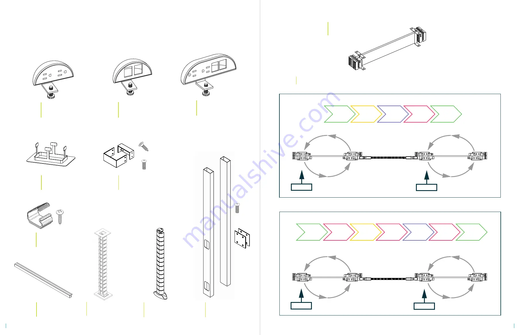
BPDH18-4
18 INCH POWER HARNESS
RECEIVES 4 DUPLEXES
C1
C2
C3
C4
C1
C2
C3
C4
1st Harness
Jumper
2nd Harness
C1
C2
C3
C4
REPEAT
STANDARD SEQUENCE
C1
C2
C3
C4
C4
C4
REPEAT
TITLE 24 SEQUENCE
C1
C2
C3
C4
C1
C4
1st Harness
Jumper
2nd Harness
ATTACH THE DUPLEXES IN THE CORRECT ORDER BY FOLLOWING THE SEQUENCE
*
START
START
START
START
C4
C4
COMPONENTS CONT.
x 4
x 4
BPP2
Power Pole
Guides Power Infeed from
the Ceiling to the Beam
x 8
VB1
Cable Vertebrae
Guides Cables from the
Floor to the Cable Tray
BPMA
Desktop Power Unit
2 Power Outlets
Clamp to the Surface Edge or
to the Grommet Hole
BPJ47
J-Channel
Mount to Surface for
Wire Management
OPTIONAL ACCESSORIES
BPPCTP
Power Pole Trim Plate
Trims the Opening Where the
Power Pole Enters the Ceiling
BPPBRK
Power Pole Bracket
Used to Anchor the Power Pole
to the Desk Frame
BPDMA
Desktop Data Unit
2 Data Ports
Clamp to the Surface Edge or
to the Grommet Hole
BMFDA
Desktop Combo Unit
2 Power O 2 Data Ports
Clamp to the Surface Edge or
to the Grommet Hole
For installation questions call
210.648.2095
or email
customerservice@mycleardesign.com
VB3
KIT-JC
J-Clip
Mount to Surface for
Wire Management
10
11


