


FieldSmart
®
Fiber Active Cabinet (FAC) 400
Installation Manual
_________________________________________________________
Proprietary Information: Not for use or disclosure except by written agreement with Clearfield.
90
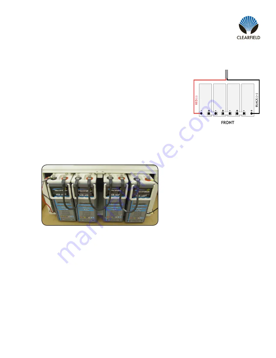
Connect the battery power cables as follows:
a.
Remove the protective caps from the cable ring lugs.
b.
Attach the black cable to the positive (+) terminal post at the positive
end of the string.
c.
Attach the red cable to the negative (-) terminal post at the negative end
of the string.
ALERT!
Check all connections carefully to verify correct wiring polarities.
d.
Install the temperature sensor cable lug onto the string’s negative (-)
terminal post.
e.
Tighten the hardware on the terminal posts to the torque specified by the manufacturer.
Install the three jumper cables between the battery terminal posts using the supplied flat washers, split lock
washers, and bolts.
Before connecting the batteries, pull out one rectifier module.
Using a digital volt meter, check for correct polarity and test the battery connection between the negative and
positive battery leads:
a.
Place the red voltmeter lead on the red negative (-) battery lead.
b.
Place the black voltmeter lead on the black positive (+) battery lead.
c.
Verify that the voltmeter reads between -46 and -54 VDC.
d.
Measure the voltage difference between the power system and the battery string. The voltage difference
should be less than 3V. If the voltage difference is greater than 3V, check for connection integrity, replace
bad battery cell as applicable, and retest the voltage. Reconnect the battery power cables to the power
supply
leads.
Step 6:
Step 7:
Step 8:
Step 9:


