background image

13

FieldSmart

®

 Fiber Scalability Center (FSC)

__________________________________________________________

Installation Manual

Direct: 763.476.6866 • National: 800.422.2537 • www.SeeClearfield.com • techsupport@clfd.net 

Manual 009246 REV J - Feb 2020

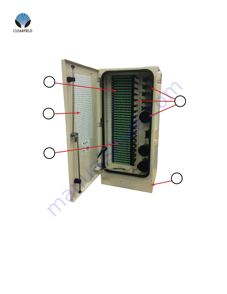
1.  Designation Card

2.  Distribution Cassettes

3. 

Feeder Cassettes

4. 

Fiber Management Rods and Spools

5. 

Riser (Available in 4” and 12”)

6. 

Not Shown - Access Panel (Included on 

12” Riser)

432 Cross-Connect Cabinet: Front View

1

2

3

4

5

Summary of Contents for FieldSmart FSC PON Cabinets 1152 Port

Page 1: ...FieldSmart Fiber Scalability Center FSC Installation Manual _______________________________________________________ Manual 009246 REV J Feb 2020 ...

Page 2: ...et Mounting 20 Preparing the Enclosure Base for Installation 20 Ground Locate Box 21 Mounting Base on Concrete Pad Vault Lid 22 Mounting Base to CraftSmart HDPE Lids 23 Mounting Enclosure on Base 26 Pole Mount Installation 27 FieldSmart FSC Pole Mount Under Plate Kit 30 Wall Mount Installation 31 Cable Installation and Splicing 33 Grounding the Enclosure 41 Optional Top Cable Entrance Ports 42 Opt...

Page 3: ...esigned for the outside plant environment these cabinets provide a single distribution point to distribute FTTH in urban or dense neighborhood Description Application Technical Specifications FieldSmart FSC PON Cabinets 288 Port 432 Port 576 Port 1 152 Port Dimensions without riser 32 H x 16 78 W x 16 9 D 36 67 H x 21 17 W x 16 9 D 32 H x 33 W x 16 9 D 64 H x 33 W x 16 9 D Weight 54 lbs 66 lbs 86 ...

Page 4: ...pment to the turn up of revenue generating circuits Further labor and other field costs are minimized through this craft friendly layout The FieldSmart FSC Cross Connect Cabinet is the complete solution for managing up to 1 728 fibers in most any feeder distribution ratio for an outside plant FTTx application This solution provides an interconnect environment from the feeder network and the distri...

Page 5: ...physical hub location thereby saving land maintenance and permitting expenses Service providers increase revenue by collapsing multiple locations into one centralized service point Description Application Technical Specifications Hub Collapse Cabinet Overview FieldSmart FSC Hub Collapse Cabinet 1 728 Port Dimensions without riser 32 H x 17 W x 16 D Weight 54 lbs Port Density 120 can add five addit...

Page 6: ...mers depending on the application packaging may vary Patch and splice cabinets are typically bubble wrapped and put inside of a cardboard box For patch only cabinets with pre terminated fiber tails they are bubble wrapped and attached to a pallet Risers if ordered will typically ship separately on the top of the cabinet This is done for installation purposes Note There are multiple items and small...

Page 7: ...2537 www SeeClearfield com techsupport clfd net Manual 009246 REV J Feb 2020 2 3 7 1 5 6 FSC Cabinet Component Views 1 Designation Card 2 Distribution Cassettes 3 Feeder Cassettes 4 Fiber Management Rods and Spools 5 Fiber Splitter Storage 6 Staging Plate 7 Riser Available in 4 or 12 8 Not Shown Access Panel Included on 12 Riser 4 288 PON Cabinet Front View ...

Page 8: ...t Fiber Scalability Center FSC Installation Manual __________________________________________________________ Manual 009246 REV J Feb 2020 2 3 1 Distribution and Feeder Cassettes 2 Distribution and Feeder Cable Ports 3 Grounding Bar 4 Fiber Management Rods and Spools 4 1 288 PON Cabinet Rear View ...

Page 9: ...onal 800 422 2537 www SeeClearfield com techsupport clfd net Manual 009246 REV J Feb 2020 1 Designation Card 2 Feeder Cassettes 3 Distribution Cassettes 4 Fiber Management Rods and Spools 5 Fiber Splitter Storage 6 Staging Plates 7 Riser Available in 4 and 12 8 Not Shown Access Panel Included on 12 Riser 2 3 1 5 6 4 432 PON Cabinet Front View 7 ...

Page 10: ...dSmart Fiber Scalability Center FSC Installation Manual __________________________________________________________ Manual 009246 REV J Feb 2020 2 3 1 1 Distribution and Feeder Cassettes 2 Distribution and Feeder Cable Ports 3 Grounding Bar 4 Fiber Management Spools 4 432 PON Cabinet Rear View ...

Page 11: ...6 REV J Feb 2020 7 1 3 2 1 Designation Cards 2 Feeder Cassettes 3 Distribution Cassettes 4 Fiber Management Rods and Spools 5 Fiber Splitter Storage 6 Stagin Plates 7 Riser Available in 4 and 12 8 Not Shown Acces Panel Included on 12 Riser 6 1 4 5 Note The 1 152 PON Cabinet is comprised of two 576 Cabinets stacked on top of eachother The features will be the same as the ones pointed out here 576 P...

Page 12: ...________________________ Manual 009246 REV J Feb 2020 5 4 3 1 Distribution and Feeder Cassettes 2 Distribution and Feeder Cable Ports 3 Grounding Bar 4 Fiber Management Spools 5 Access Panel on 12 Riser Only 1 2 Note The 1 152 PON Cabinet is comprised of two 576 Cabinets stacked on top of eachother The features will be the same as the ones pointed out here 576 PON Cabinet Rear View ...

Page 13: ...t 763 476 6866 National 800 422 2537 www SeeClearfield com techsupport clfd net Manual 009246 REV J Feb 2020 1 Designation Card 2 Distribution Cassettes 3 Feeder Cassettes 4 Fiber Management Rods and Spools 5 Riser Available in 4 and 12 6 Not Shown Access Panel Included on 12 Riser 432 Cross Connect Cabinet Front View 1 2 3 4 5 ...

Page 14: ...er FSC Installation Manual __________________________________________________________ Manual 009246 REV J Feb 2020 1 Distribution and Feeder Cassettes 2 Distribution and Feeder Cable Ports 3 Grounding BAr 4 Fiber Management Spools 5 Not Shown Access Panel Included with 12 Riser 432 Cross Connect Cabinet Rear View 4 3 2 1 ...

Page 15: ...ual 009246 REV J Feb 2020 1 3 2 1 Designation Cards 2 Feeder Cassettes 3 Distribution Cassettes 4 Fiber Management Rods and Spools 5 Not Shown Riser Available in 4 and 12 6 Not Shown Access Panel Included on 12 Riser 4 Note The 1 728 Cross Connect Cabinet is comprised of two 864 Cabinets stacked on top of eachother The features will be the same as the ones pointed out here 864 Cross Connect Cabine...

Page 16: ...l 009246 REV J Feb 2020 4 3 Note The 1 728 Cross Connect Cabinet is comprised of two 864 Cabinets stacked on top of eachother The features will be the same as the ones pointed out here 1 Distribution and Feeder Cassettes 2 Distribution and Feeder Cable Ports 3 Grounding Bar 4 Fiber Management Spools 5 Not Shown Riser Available in 4 or 12 and Access Panel On 12 Riser Only 1 2 864 Cross Connect Cabi...

Page 17: ...ational 800 422 2537 www SeeClearfield com techsupport clfd net Manual 009246 REV J Feb 2020 5 4 1 3 2 1 Designation Card 2 Distribution and Feeder Cassettes 3 Fiber Management Rods and Spools 4 LGX Card Areas 5 Riser Available in 4 and 12 6 Not Shown Access Panel Included on 12 Riser HCC Bracket P N 014375 Hub Collapse Cabinet HCC Front View ...

Page 18: ...al __________________________________________________________ Manual 009246 REV J Feb 2020 6 4 1 3 2 1 Distribution and Feeder Cassettes 2 Distribution and Feeder Cable Ports 3 Grounding Bar 4 Fiber Management Spools 5 LGX Card Areas 6 Riser Available in 4 and 12 7 Not Shown Access Panel Included on 12 Riser Hub Collapse Cabinet HCC Rear View 5 ...

Page 19: ...erally defined by the approximate cover dimensions The vault actual measurements will differ The dimensions above for determining the size of the excavation provide sufficient volume for accommodating the maximum recommended select backfill The volume of excavation would be reduced if a lesser volume of backfill material were chosen Excavate the hole to appropriate dimensions with a mechanical exc...

Page 20: ...e base and remove any packaging materials They are typically assembled and packaged on top of FieldSmart Cabinets There are both a 4 and 12 riser kit available to each style cabinet All have pre cut vent holes and the 12 has an access door 288 PON 432 Cross Connect Hub Collapse Cabinets 4 12 Access door facing rear of cabinet 4 12 Access door facing front and rear 4 12 Access door facing front and...

Page 21: ...ability to locate distribution cables without the risk of damage to live circuits by opening the cabinet Through the use of the main cabinet ground bar and Clearfield s ground stud kit P N 016953 the customer can have a locate point on the outside of the cabinet Clearfield suggests To install a ground stud drill a 1 4 hole in the base of the cabinet and insert the stud Tighten and seal with silico...

Page 22: ...the anchor alignment mount per your local practice Note Anchors are supplied by the customer to comply with local rules and regulations Be sure to use anchors with the diameter dimensions which will fit the holes in the base riser Optionally you may choose to use the round cut outs for more flexibility in mounting the base Place the rectangular washer plates found in the hardware package onto the ...

Page 23: ...nderside of the vault lid via two zip ties using these two pre drilled base mounting holes Mounting Base to CraftSmart HDPE Lids Locate the bolt hardware kit supplied with each CraftSmart vault that have cut outs for the FieldSmart FSC Cabinets All CraftSmart HDPE Vault Lids come with a precut cable entrance hole and pre drilled base mounting holes so no drilling is required in the field 24 x 36 V...

Page 24: ...7 www SeeClearfield com techsupport clfd net 24 FieldSmart Fiber Scalability Center FSC Installation Manual __________________________________________________________ Manual 009246 REV J Feb 2020 288 PON 432 Cross Connect Hub Collapse 432 PON ...

Page 25: ...t 763 476 6866 National 800 422 2537 www SeeClearfield com techsupport clfd net Manual 009246 REV J Feb 2020 30 x 48 Vault Accepts 576 and 1 152 PON cabinets 864 and 1 728 Cross Connect cabinets in addition to 288 and 432 PON cabinets 432 Cross Connect cabinets and Hub Collapse cabinets 576 1 152 PON and 864 1 728 Cross Connect ...

Page 26: ...lts washers and lock washers Assure the enclosure is oriented properly to the base and then insert the bolts through holes in the corners of the enclosure Insert all four bolts before tightening them with a wrench Check for and remove all tape cardboard and foam supports used during shipping Use the J bolts supplied in the bolt kit to attach the cabinet base to the vault lid J bolts are installed ...

Page 27: ...st to the pole Note A second hoist plate is included for use if the cabinet will be raised by a hoist 2 Locate the toothed bracket that has the mounting holes in the flange and mount it to the base below the previously installed hoist plate using the included hardware 3 Determine the top height of the cabinet Drill a 5 8 hole 8 inches below the anticipated height of the cabinet all the way through...

Page 28: ...f the pole It is suggested to add 3 to the diameter of pole for rod length Note Clearfield does not recommend using lag bolts to mount cabinet to pole Clearfield recommends using hardware with a minimum of 5 8 diameter Care should be taken to avoid over tightening and deforming the hoist plate Lock tight red should be used on nuts to prevent loosening of nuts Make sure the thread rod nut does not ...

Page 29: ... Direct 763 476 6866 National 800 422 2537 www SeeClearfield com techsupport clfd net Manual 009246 REV J Feb 2020 6 Level cabinet and drill 5 8 hole through lower bracket and pole and install 5 8 rod washers and nuts Note Care should be taken to avoid over tightening and deforming the hoist plate 7 Cabinet Fully Mounted ...

Page 30: ...installed 2 3 4 5 6 The kit comes with two plates with stenciled templates for multiple sizes of conduit The standard knock out is for a 2 conduit If larger conduit is being used cut the plates to the appropriate size After plates have been prepared for correct conduit install one side of the plate onto the bottom of the cabinet Install conduit and cable Secure conduit with cable clamp provided in...

Page 31: ...to the cabinet and two mounting brackets Wall mounting the cabinet will require a 5 8 socket a drill and drill bit and mounting hardware of your choice All cabinet variations will require a riser to be installed to attach the bottom mounting bracket 1 Using the provided hardware and a 5 8 socket attach one of the hoist plates to the side of the cabinet that will be facing the wall Tighten firmly I...

Page 32: ...location Measure down 8 inches from the mark you made for the top of the cabinet Mark this loca tion drill your pilot hole and use it to mount the second top mounting bracket Note Be sure not to over tighten hardware as the mounting bracket could deform Lift the cabinet and slide the top mounting bracket under the hoist plate at the top of the cabinet until fully seated Level the cabinet prior to ...

Page 33: ... riser Determine which port s in the feed through entrance plate will be used to install the cable s Note If you intend to bring more cables into the cabinet at a later date it is recommended that you work from back to front installing initial cables as far in and as close to the cabinet bulkhead as possible 1 2 3 If the entrance plate already has a cable installed you will need to loosen the seal...

Page 34: ...t is around the cables and below the entrance plate before proceeding Compression Fitting Grommet Cable Size Inches Small Black Grommet 0 3 0 4 Medium Black Grommet 0 41 0 5 Gray Grommet Comes Pre Installed 0 51 0 79 Large Black Grommet Comes Pre Installed 0 71 0 98 6 Select the compression fitting grommet size that most nearly fits the cable to be installed The grommets are included in the ship a...

Page 35: ...ng Push the new one in to place Ensure new grommets are installed with the tapered side up see pictures Note It is sometimes easier to remove the grommet by using a blunt ended tool to push at it from the bottom inside the sealcon Take care not to damage the grommet 2 1 6 5 4 3 Ensure the O ring on the underside of the sealcon is present before installation Loosen or if needed remove the dome nut ...

Page 36: ...cking nut underneath the entrance plate If the sealcon dome nut is not already installed install after tightening lock nut but do NOT tighten to secure cable Note Clearfield recommends the use of a set of sealcon wrenches P N s 013190 40mm and 013191 42mm to properly tighten the sealcon lock nut and dome nut These feature an open channel which allows the wrench to slide over cables and onto the se...

Page 37: ...ing the buffer tubes 11 feet from the outer jacket and staggering the marks 1 longer for each buffer tube 11 blue 11 1 orange 11 2 green etc This will allow for the different lengths required for each buffer tube to reach its cassette after storing the slack around the spools in the cabinet Remove all Clearview Cassettes from the cabinet that are to be spliced if required 14 15 See the Clearview B...

Page 38: ...__________________________________________________ Manual 009246 REV J Feb 2020 Pull the extra unopened cable slack back through the sealcon and out of the cabinet If utilizing a strength member clamp bring the strength member over to the clamp and secure tightly 17 18 Tighten the dome nut on the sealcon securely being careful not to damage the threads 19 ...

Page 39: ...rouped buffer tubes first over the top radius limiter Figure 1 Continue routing the grouped buffer tubes down and around the bottom radius limiter Figure 2 Finish routing the grouped buffer tubes back up and around the top radius limiter Repeat until all slack is stored 22 Figure 1 Figure 2 After routing the buffer tubes install the cassette into the bulkhead in the appropriate port locations from...

Page 40: ... Feb 2020 288 PON Routing Rear of Cabinet The suggested cable routing for feeder and distribution cables is in the rear of the cabinet Note Cables should enter cassettes on side closest to cable management not crossed over 576 PON Routing Rear of Cabinet Suggested cable routing for feeder and distribution cables in the rear of the cabinet Note Cables should enter cassettes on side closest to cable...

Page 41: ...REV J Feb 2020 Grounding the Enclosure Clearfield recommends that all grounding installations follow the per local practice guidelines for each application A grounding plate and lug is located in the lower left corner of the rear of the cabinet The cabinet can be grounded via the large lug attached to the plate using a 6 gauge or larger wire Individual cables can be grounded using the remaining st...

Page 42: ...ing plug from the hole 3 Install 1 NPT sealing plug and correct size cable grommet tighten to cabinet 4 Install cable through grommet plug and into cabinet Note Midspanning of cable cannot be done using the top entry ports If the cabinet does not have factory drilled holes the following can be done to field install to the cable entrance ports 1 Locate the dimples on the top of the cabinet there ar...

Page 43: ...binet Then route the fibers to the top most radius spool in the upper right side of the cabinet loop the fibers over the radius limiter and across the two support fingers Install the staging plate into the brackets located in the top corners of the cabinet Slide any excess slack in the fibers back to the bottom of the cabinet if installed correctly the fiber will hang from the splitter module and ...

Page 44: ...PON Cabinet 288 PON Cabinet The 288 576 and 1152 PON Cabinets will allow up to 2 staging plates in each staging area at the top of the cabinet One staging plate can be installed with the foam cradle in place or you can remove the foam cradle and replace with the foam strips on each end of the staging plate This will allow two staging plates to fit in each staging area Choose your desired port to c...

Page 45: ...Clearfield com techsupport clfd net Manual 009246 REV J Feb 2020 432 PON Cabinet The 432 PON Cabinet has a different splitter routing scheme than the other FSC Cabinets available from Clearfield The top staging plate area will hold two staging plates with the foam cradles in place Splitter Cage Staging Plates Splitter Leg Routing Splitter Cage Staging Plate Staging Plate ...

Page 46: ... Installation Manual __________________________________________________________ Manual 009246 REV J Feb 2020 Jumper Routing 864 Cross Connect Cabinet 432 Cross Connect Cabinet Shown below are routing diagrams for jumpers in Clearfield s 432 and 864 Cross Connect Cabinets The 1728 Cross Connect would function in the same manner ...

Page 47: ...ld com techsupport clfd net Manual 009246 REV J Feb 2020 Cabinet Accessories Mid Span Opening Feed Trough Plate Kit Grommet Tape Feed Through Plate A Feed Through Plate B x2 Clamping Bracket Foam Sealing Plug Foam Gasket Cable Clamp Shells a 1 b 3 4 c 1 2 Clamp Mounting Screw Kit Mounting Bolts Strength Member Clamp Plate Use is Optional 1 2 3 4 5 6 7 8 9 10 7 1 3 2 6 8 4 5 9 10 ...

Page 48: ...ped using either a mid span opening or the end of the cable 1 Locate the green clamp shells and corresponding 1 4 20 mounting screws from the ship along hardware The clamp shells are used in same size pairs Avoid using a clamp that is too small and does not easily close around the cable Use the next larger clamp and grommet tape Grommet tape should be applied to the green clamp shell prior to inst...

Page 49: ...om of the cabinet Bring your cables up through the hole and slide them into the slots in feed through plate A Note It is recommended to work from back to front so cables installed at a later date are easier to access 5 Wrap grommet tape around the cable at the mark until you have an overall outside diameter of 1 3 4 4 Feed through plate B can then be slid onto the cable followed by the cable clamp...

Page 50: ...choosing to use the strength member clamp plate the plate will go in behind the cable clamps and the clamp mounting screws will secure both in place to the cable clamp bracket 7 Once all your cables are secured to the cable clamp bracket attach the entire kit to the base of the cabinet using the 6 kit mounting bolts and tightening them evenly to avoid warping the plates 8 The unused holes can be p...

Page 51: ...e in most hardware stores 1 Align the debris shield with the top of the cabinet using the dimbles as a guide for how far it should overhang The dimples will prevent you from installing the debris shield too far back 2 Self drilling screws are provided with the debris shield though their use is optional Use them to secure the shield for additional strength 3 If cabinet is equipped with additional e...

Page 52: ...ching of the end face Learn the process of cleaning properly Note It is NOT recommended to use isopropyl alcohol to clean the end face Cleaning an SC LC Connector Cleaning the End Face Place one wiping paper on QbE 2 FiberSafe Cleaning Platen Figure 1 Apply small amount of precision cleaner about 1 in diameter with Electro Wash MX pen on to one end of the wipe Figure 2 Hold end face at a 90 degree...

Page 53: ...pter AND the Adapter Itself Lightly moisten the fiber optic swab 2 5mm 38542F or 1 25mm 38040 by spotting a small amount about 1 of Electro Wash PX or Electro Wash MX pen onto the QbE Hold the tip of the swab onto the wetted area and hold for a count of 1 2 3 4 5 Insert the swab into the adapter to the connector press lightly against the connector twist 2 3 times remove and discard Dry with a seco...

Page 54: ... pins with this or an equivalent type swab Cleans ALL MTP MPO connector end faces This swab also cleans the pins of the male connector Lightly spot a QbE 2 wipe on the platen with Electro Wash PX Fiber Optic Cleaner the FiberWash or MX Pen Lightly touch short side of the MTP MPO Connector Swab to the wetted area 3 5 secs to absorb some cleaning solution DO NOT over saturate the swab Wipe connector...

Page 55: ...t pins Cleaned like a single fiber connector using a cleaning platform The receptacles will be cleaned as long as you are using a combination clean ing process as recommended Again using a platen moisten the platen with cleaning solvent on one end to accommodate 3 swipes of the MPO female endface Holding the connector If APC slightly at an angle to accommodate for 8 angle swiping with medium press...

Page 56: ...face separately or through the adapter Slightly engage probe by pulling back but do not allow to click Lightly spot a QbE 2 wipe on the platen with Elec tro Wash PX Fiber Optic Cleaner this will help alleviate over saturation of the material Lightly touch the tip of probe and release Wipe Material Wet End Face Dry Insert connector or insert probe though adapter and click 2 3 times to move past the...

Page 57: ...the option of Clearfield Inc shall constitute the exclusive sole remedy for a breach of this limited warranty Clearfield shall not be liable under any circumstances for any special consequential incidental punitive or exemplary damages arising out of or in any way connected with the product or with agreement to sell product to buyer including but not limited to damages for lost profits loss of use...

Page 58: ...ipment supplied Every effort has been made to keep the information contained in this document current and accurate as of the date of publication or revision However no guarantee is given or implied that the document is error free or that it is accurate with regard to any specification Technical Support Clearfield Inc can be contacted for any issues that arise with the supplied product If you need ...

Reviews: