background image

19

Installation

~ LCD Programming

Technical Services Group 

~ 1-800-283-5936 (USA) ~ 1-801-974-3760

F

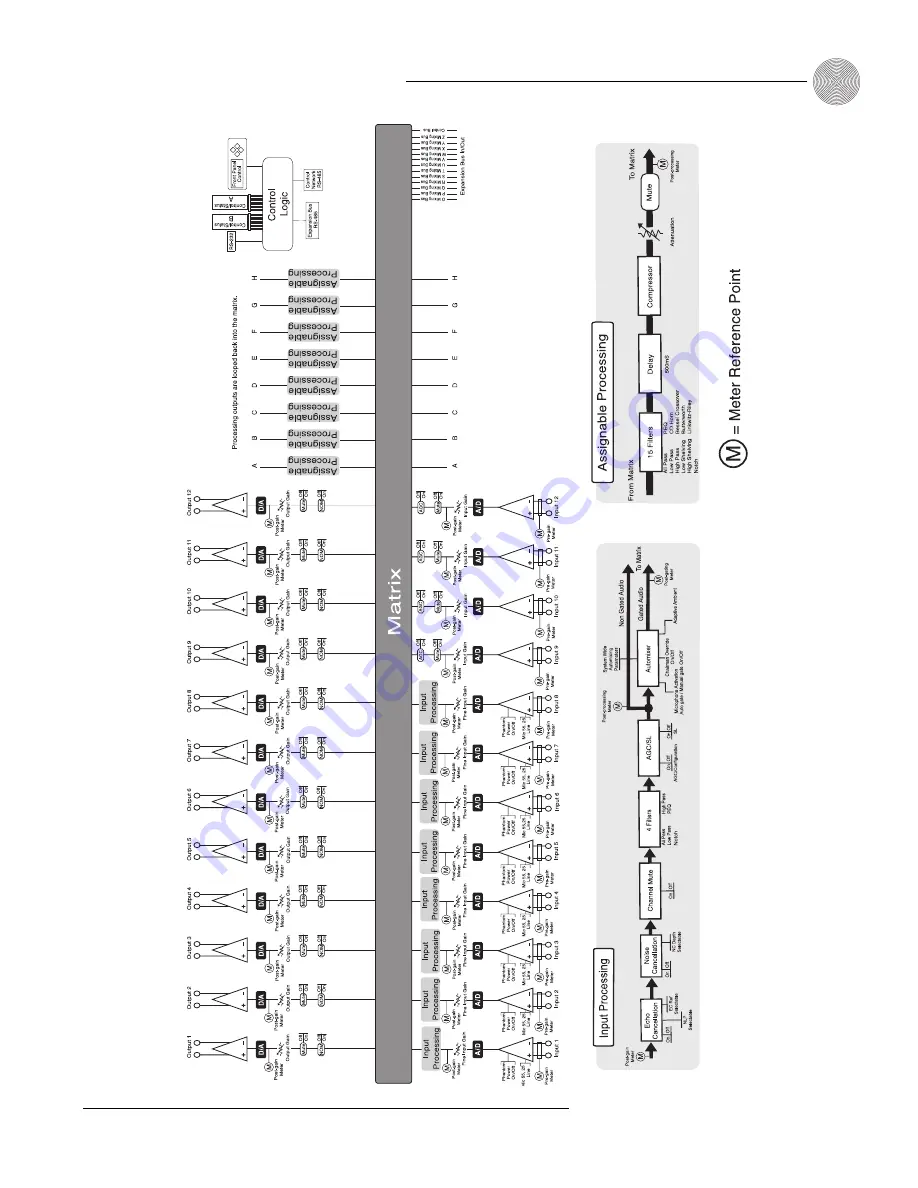
igure 2.7.

Meter Reference P

oint diagram

Summary of Contents for XAP 800

Page 1: ...XAP 800 Audio Conferencing System Installation Operation Manual ...

Page 2: ... be reproduced in any form or by any means without written permission from ClearOne Communications Printed in the United States of America ClearOne Communications reserves specific privileges Information in this document is subject to change without notice XAP 800 Installation and Operation Manual ClearOne Part No 800 151 101 May 2005 Rev 4 1 ...

Page 3: ...oup 3 Unpacking 4 Controls and Connections 4 Front panel 4 Rear panel 5 Networking 7 Expansion bus 7 Operational Requirements 8 Power 8 Equipment placement 8 Environmental 8 G Ware requirements 8 CHAPTER 2 Installation 9 Hardware Setup 9 To connect the unit 10 Networking Units 11 Expansion bus connections 11 Device IDs 12 Mixer mode 12 LCD Programming 13 LCD menu tree 13 System menu 14 RS 232 menu...

Page 4: ...en 27 Matrix Screen 29 Audio Routing 30 Expansion bus O Z routing 30 Process A H routing 30 Cross point attenuation 30 Matrix report 31 Inputs and Outputs 32 Inputs 1 8 32 Inputs 9 12 44 Outputs 1 12 46 Expansion Buses 48 From Expansion Bus O Z 48 To Expansion Bus O Z 48 Processing 49 Processing A H 49 CHAPTER 4 Advanced Configuration 55 Presets 55 Overview 55 Creating Presets 55 Running presets 6...

Page 5: ...ing Views 75 Gate View 75 Meter Views 76 CHAPTER 6 Control 77 GPIO Builder 77 Control Status A 77 Remote Builder 78 XAP IR Remote 78 ClearOne Control Panels 79 RS 232 Port 82 Remote modem access 82 Serial commands 82 Command Strings 83 APPENDICES 85 Appendix A Specifications 85 Appendix B Pinouts 87 Appendix C Control Panel 91 Appendix D Accessories 93 Appendix E Serial Commands 94 Appendix F Warr...

Page 6: ...vi Technical Services Group 1 800 283 5936 USA 1 801 974 3760 ...

Page 7: ...nitors each mic independently observing ambient levels and making decisions based on each mic s environment Thus the input for a mic located in a highly reverberant part of a conference room is gated mixed and processed to compensate for the changes in that area and reduce echo and noise This improves audio quality and decreases the possibility of feedback The XAP 800 facilitates local and remote ...

Page 8: ...ing an analog output This added flexibility further enhances echo cancellation performance Improved noise cancellation Our industry leading noise cancellation keeps background noise to a minimum while retaining top level voice quality echo cancellation performance and full duplex capability Front panel gain and mute control Now gain and mute adjustments can be made from the front panel Using these...

Page 9: ...and Customer Service Telephone 1 800 945 7730 USA or 1 801 975 7200 Fax 1 800 933 5107 USA or 1 801 977 0087 E mail sales clearone com ClearOne Communications EuMEA GmbH Leonhardstr 16 18 D 90443 Nuremberg Germany Telephone 49 911 955159 0 Fax 49 911 955159 10 E mail global clearone com Product registration Please register your XAP 800 online by visiting ClearOne Technical Support at www clearone ...

Page 10: ... 800 unit Front panel A LCD This display is for XAP 800 setup in conjunction with the four associated front panel buttons B C and D Baud rate and flow control must be configured from the front panel see the LCD Menu Tree on page 13 for the location of these in the menu system Other functions accessed via the front panel include system options RS 232 configuration troubleshooting and level readings...

Page 11: ...r branch of the XAP 800 s LCD menu tree G LED 1 8 These LEDs indicate Inputs 1 8 gate status Rear panel A Power This power module accommodates power ranging from 100 240VAC 50 60Hz The module uses an IEC type connector No switching is required B Inputs 1 8 These Phoenix block connectors are for connection of eight mic level or line level selectable inputs These connectors are typically used for mi...

Page 12: ...1 12 These three pin Phoenix connectors are for connection of twelve line level balanced outputs with three pin Phoenix connectors These outputs are typically used for connection to VCRs tape recorders amplifiers codecs phone hybrids and other audio devices These outputs may be configured to contain any combination of gated and non gated inputs The nominal output level is 0dBm F Inputs 9 12 These ...

Page 13: ...uses These four audio buses are defaulted as the mic mix buses they can communicate the NOM count and mic mixing parameters across the network to other XAP 800s All gated mics are routed to the 0 bus by default S Z buses These eight buses are defaulted as auxiliary mix buses They are used to route auxiliary audio such as from a CD player or VCR to and from other units on the network These buses ar...

Page 14: ...ssories Environmental The XAP 800 can be safely operated in a room with varying temperatures between 32 F 0 C and 110 F 43 C G Ware requirements ClearOne s G Ware software requires the following minimum system configuration Minimum RAM requirement is determined by the operating system Windows 95 OSR2 64MB Windows 98 64MB Windows ME 64MB Windows NT 64MB Windows 2000 128MB Windows XP 256MB PII 200MH...

Page 15: ...s creating an expansion bus E bus network assigning device ID numbers selecting the mixer mode and using the front panel LCD menu The diagram below illustrates the typical connections that are made for a single unit XAP 800 system The default routing settings in the G Ware Matrix Screen allow the XAP 800 to work out of the box for this type of installation CHAPTER 2 Installation Hardware Setup Fig...

Page 16: ...onnector opening and tighten down the top screw Inputs 1 8 B Mic or line level inputs Inputs 9 12 F Line level inputs only Outputs 1 12 E Line level outputs 4 If you are using a ClearOne Remote Panel wire it to the RS 485 port C using the provided four terminal Phoenix push on connectors 5 Plug in the XAP 800 to complete the installation The power output A will operate at any level between 100 240...

Page 17: ...en the total length between the two XAP 800s is 100 feet which is beyond the maximum 80 foot limit To create an expansion bus network 1 Plug the expansion bus terminator in the Expansion Bus In connector of the first unit in the network 2 Connect the RJ 45 jumper cable or Cat 5 twisted pair cable to the Expansion Bus Out connector of the first unit in the network and Expansion Bus In connector of ...

Page 18: ...s prevents audio from being received from units above the master unit in the network However global control of the system is still maintained by whichever XAP 400 800 or PSR1212 unit is connected to a control device through its RS 232 or RS 485 ports Control is not affected by master slave designations In Figure 2 5 the third unit in the network is a master It prevents the audio from the first and...

Page 19: ...oring When power is applied to the XAP 800 the LCD panel will first read INITIALIZING If an error is displayed contact technical support When initialization is complete XAP 800 is displayed on the top line and Unit 0 is displayed on the bottom line LCD menu tree The menu tree features five main menus each with submenus These branches typically end when an adjustable parameter or viewable value is ...

Page 20: ...If the Meter button is pressed while a parameter is being adjusted the LCD will switch to the Meter menu System menu There are eight system level parameters see Figure 2 6 Select Preset Run Macro Lock Panel Set Passcode Device ID Mixer Mode Unit ID and Firmware Version Select Preset The Select Preset menu item allows for one of 32 preprogrammed presets to be selected for XAP 800 use To select a pr...

Page 21: ...tion Device ID The XAP 800 s device ID is set from this menu There are eight device ID selections to choose from 0 7 Select the network position you want to use Within a single site you must assign different device ID numbers for each XAP 800 unit See Device IDs page 12 Unit ID The Unit ID menu selection allows you to access the read only address set at the factory This unique ID number identifies...

Page 22: ...ss through device such as a modem To avoid communication errors ClearOne strongly recommends that you connect all DB9 pins and enable flow control when connecting to a PC Enable Modem This parameter configures the RS 232 port for connection of a modem When On is selected the XAP 800 will send an initialization string to the modem on power up and require a password before data transfer is allowed t...

Page 23: ...eters on the XAP 800 Select the meter you want to monitor and press Enter ERLE This submenu allows monitoring of the ERLE meters on the XAP 800 Select the meter you want to monitor and press Enter Default Meter This submenu determines what is displayed on the LED meter when a meter is not specifically selected elsewhere in the Meter menu The default is Output 12 The Meter Reference Point diagram o...

Page 24: ...der the Outputs menu Mute and Gain To access these submenus you must first select the output Choose from Outputs 1 12 Use the and buttons to select the Outputs menu then scroll through the options and press Enter when you reach the desired option Mute This submenu allows you to turn mute on or off default for the selected output Gain This submenu allows you to adjust the gain for the selected outp...

Page 25: ...19 Installation LCD Programming Technical Services Group 1 800 283 5936 USA 1 801 974 3760 Figure 2 7 Meter Reference Point diagram ...

Page 26: ...20 Technical Services Group 1 800 283 5936 USA 1 801 974 3760 ...

Page 27: ...nstall G Ware and create a site It also describes all configurable parameters of your system These descriptions are designed to be used as a guide as you make adjustments for your particular installation It is not necessary to configure all parameters ClearOne s G Ware software requires the following minimum system configuration Minimum RAM requirement is determined by the operating system Windows...

Page 28: ... install G Ware 1 Boot the PC to the Windows operating system Ensure that all other programs or applications are closed Insert the Audio and Video Products CD into the CD ROM drive If the Autorun feature is enabled on the PC the ClearOne Welcome window opens Click the Software tab and select G Ware If the Autorun window does not open open the Windows Start menu and choose Run Type drive clearone e...

Page 29: ... company location room and description using the Tab key or mouse to select each field 3 Click the Comm tab Select the COM port baud rate and flow control you want to use ClearOne recommends that you leave Flow Control set to Hardware The Software setting is not supported by XAP PSR units and is typically used with modems 4 If you plan to use a modem select Use Modem and enter the phone number ini...

Page 30: ...network and place them in the Site pane See Figure 3 11 Note When connecting to your site you can choose to sync to Unit s or Document If you sync to the Unit s you will overwrite your G Ware site file with the current settings of the unit s If you sync to the Document you will overwrite the settings in your units with the settings you have saved in the site file Choosing to sync to Document will ...

Page 31: ...the proper unit when there are multiple XAP 800s on a network 3 Select the Unit Type default is slave See page 12 for more information 4 Select an input output or processing channel to be the Default Meter on the front panel meter LED when a channel is not specifically selected 5 Select the Meter Refresh Rate which determines how quickly the XAP 800 updates meter information default is 100ms range...

Page 32: ...acro Editor Presets and Macros that are locked do not require the password to be run However the password is required to make changes 11 Select the Front Panel Lock Mode Unlock Panel leaves the front panel controls unlocked Lock Panel locks the front panel immediately Lock When Timeout locks the front panel after it is inactive for the specified number of minutes The range is from 0 15 minutes 5 m...

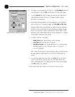
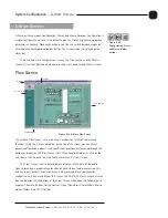
Page 33: ...essed through the buttons and labels on the Flow Screen itself If you have multiple units click on the unit icon in the Site pane to access that particular unit s Flow Screen The Flow Screen shows a detailed block diagram of the path of the audio signal presenting a graphical explanation of each stage of audio processing Mic and line inputs outputs expansion buses and processing block configuratio...

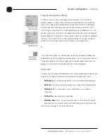
Page 34: ...nt to apply all settings of a selected input to the rest of the inputs select Apply to All S The Safety Mute feature in G Ware enables you to mute all outputs if feedback or audio problems occur during the configuration process To use Safety Mute click the Safety Mute button on the G Ware toolbar Then find and correct the cause of the problem Click the Safety Mute button again to unmute the output...

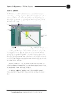
Page 35: ...nput and green all other inputs The amount of attenuation is also shown in the cross point cell Black cell are restricted routing paths which prevent E bus and Processing channels from being routed back to themselves The numbers and letters along the top and left side of the matrix show the cross point coordinates The input number or letter and the output number or letter will be highlighted blue ...

Page 36: ...ation within the unit The XAP 800 has 12 digital mix minus buses O R buses are defaulted as the mic mix buses and can communicate the NOM count Gated mics are default routed to the O bus S Z buses are defaulted as the auxiliary mix buses They are used to carry auxiliary audio such as that from codecs and XAP TH2s These buses are used as mic mix buses when NOM count is not required Process A H rout...

Page 37: ... copy a single cell or the entire matrix using the shortcut menu options To copy and paste a cross point to multiple cross points press Ctrl C to copy or right mouse click Then press Ctrl V while holding down the left mouse button and drag the mouse over the cross points to which you want to copy the settings Matrix report When you finish audio routing you can print a detailed report of the matrix...

Page 38: ... light gray The many configurable properties of mic inputs are defined in this section Mute Mute mutes the input channel The light on the button illuminates red when Mute is activated Default is Off unmuted AGC SL AGC SL opens the Automatic Gain Control Speech Leveler window If Speech Leveler or AGC is enabled the light on the button illuminates green Default for both is off Inputs and Outputs Fig...

Page 39: ...eshold determines the decibel level at which you want the AGC to engage Setting the threshold toward the higher end of the scale near 0 reduces background noise to a greater degree The Response Time is measured in milliseconds Target Level and Threshold are both RMS P Pwr Phantom Power Phantom Power toggles the phantom power on and off Phantom power is an auxiliary power source to power certain ty...

Page 40: ...ler will be able to reference both signals This means you don t need to use a dedicated output to combine signals Or you may have mics routed to the PA output but you don t want the echo canceller to reference this audio By using a virtual reference the echo canceller can sample all signals routed to the PA output minus the mic signals To create a virtual reference 1 Select the input signals you w...

Page 41: ...cibels It is an average meter that updates only when a signal is present NC The NC button on the selected input in the Inputs 1 8 window opens the Noise Canceller window The noise canceller reduces ambient noise in the signal with no noticeable degradation in signal quality To use noise cancellation click Enable Noise Canceller then adjust the Cancellation Depth to the setting which provides the b...

Page 42: ...enter frequency range is 20Hz to 20kHz with resolution to 1Hz or four places whichever is larger Bandwidth is from 05 to 5 octaves in 01 octave increments Level is fixed at 80dB PEQ parametric equalizer Center frequency range is 20Hz to 20kHz with resolution to 1Hz or 4 places whichever is larger Bandwidth is 05 to 5 octaves in 01 octave increments Level range is 15 to 15dB in 0 5dB increments Fre...

Page 43: ...r from the graph Table View Table View toggles between the Graph and the Table views of the Inputs 1 8 Filter window The Table view displays the selected filter settings in table format You can configure filters from this view as well as in the graph view To configure filters 1 In either the graph or table view select the filter type from the Type list Note that the configurable filter parameters ...

Page 44: ... gate off Default is off Adaptive Ambient Adaptive Ambient adjusts the ambient reference level as noise and room conditions change When adaptive ambient is on the mic channel monitors the ambient noise level on the input and adjusts the ambient level reference automatically This means that the gate threshold level automatically increases or decreases based on back ground noise If Adaptive Ambient ...

Page 45: ...ge is from 1 to 8 0 seconds Default is 3 seconds Off Attenuation Off Attenuation sets the amount of level reduction applied to a channel when it is gated off The range is from 0 to 50dB Default is 12dB Ambient Level Ambient Level is available only if the Adaptive Ambient feature isn t enabled Use Ambient Level if you want to specify a fixed reference point rather than one that adjusts for backgrou...

Page 46: ...n bus output you want to use as the PA reference You can also open this window from the toolbar If you select a virtual echo cancellation reference point the Virtual Reference window will open This window allows you to select which signals will be used by the four virtual reference points Virtual references are used when you need to reference multiple outputs The routing matrix portion of this win...

Page 47: ... groups span two or more units global gating groups the settings must be the same for each unit attached to the global gating group Mic inputs are routed to Global Group A by default To assign a gating group Select the Internal or Global group the mic input will belong to or select None To configure gating group settings 1 Click the Gating Control button on the toolbar This opens the Gating Contro...

Page 48: ...llows you to select which mic input the XAP 800 leaves on when all mics gate off If Off is selected all mics will gate off when no audio is present It is preferable in most applications to leave a mic on so the remote participants don t think they have lost their audio connection Off is typically only used when you are conferencing multiple sites and need to reduce background noise 5 Click the Gat...

Page 49: ...signal to noise ratio without clipping the signal Meters There are four meters on each mic line input to assist with setup and level control Select the meter check box to enable the meter All input meters are peak level Pre Gain Pre Gain meter indicates the input s level before gain adjustments Meter range is from 85 to 35dB when 55dB gain is selected 55 to 5dB when 25dB gain is selected and 65 to...

Page 50: ...ect an input channel click a blank area in the input pane If you click on the input label a secondary window will open allowing you to rename the input The background color for the selected input channel will be light gray The configurable properties of these inputs are defined in this section Mute Mute mutes the input channel The light on the button illuminates red when Mute is activated Default ...

Page 51: ...st an input s gain directly affects sound quality The optimal input gain setting is one which is adjusted as high as possible above the noise floor without introducing clipping Clipping can cause distortion which can damage amplifiers and loudspeakers To adjust the input level properly place a signal on the input at the maximum level it will generate Adjust the input gain until the peak level of t...

Page 52: ... the output pane If you click on the output label a secondary window will open allowing you to rename the output The background color for the selected output channel will be light gray The configurable properties of these outputs are defined in this section Mute Mute mutes the output channel The light on the button illuminates red when Mute is activated Default is off unmuted NOM NOM constant gain...

Page 53: ... commands absolute gain commands can exceed the min and max limits Min Max limits apply to all serially connected control devices and prevent users from adjusting levels beyond the min max levels provided relative gain commands are used Optimizing output gain structure How you adjust an output s gain directly affects sound quality The optimal output gain setting is one which is adjusted as high as...

Page 54: ...mation and close the window To Expansion Bus O Z Click the To Expansion Bus O Z button on the Flow Screen to open the To Expansion Bus Labels window You can also access this window from the Matrix Screen Enter the names you want to use for each expansion bus then click OK to save the information and close the window Expansion Buses Figure 3 50 From Expansion Bus Labels window Routing of audio to t...

Page 55: ...n the Process pane If you click on the Process label a secondary window will open allowing you to rename the processing block The background color for the selected processor will be light gray The configurable properties of these processors are defined in this section Mute Mute mutes the processor The light on the button illuminates red when Mute is activated Default is off unmuted Processing Figu...

Page 56: ...ivate the compressor Group Use the slider to assign this compressor to a compressor group The default is None When you assign a compressor to a compressor group such as a group of three configured for bass midrange and treble the compressors will monitor each other When one compressor channel compresses all compressors in the group compress together When configured properly this results in a smoot...

Page 57: ...s 1 1 Attack Attack determines how quickly compression is enabled It is calibrated in milliseconds The range is 0 to 100ms in 5ms steps Default is 10ms Release Release determines how quickly compression is disabled The range is 100ms to 2 seconds in 5ms increments Default is 500ms Input meter This peak meter shows the level of the signal as it enters the compressor Compression meter This peak mete...

Page 58: ... that reflects the changes you want to make You can continue to add filters to the graph and track their relationships to each other to design a system with the sound characteristics necessary for good audio Phase Phase plots the phase response of the frequency response of the selected filter Bypass Bypass All bypasses all filters Add Filter Add Filter adds a filter to the graph Remove Filter This...

Page 59: ...cers Delay Click Delay to open the Delay configuration window Delay calibrates the amount of signal delay introduced based on the length the distance between the source and audience and temperature you enter For example different speaker drivers within a speaker enclosure might be located different distances from the listening area because of design constraints within the box You can set up to 500...

Page 60: ... signal is present Min Max limits Use the yellow and blue upper and lower limit arrows on the Gain scale to create minimum and maximum gain level limits These limits only apply when using relative gain commands absolute gain commands can exceed the min and max limits Min Max limits apply to all serially connected control devices and prevent users from adjusting levels beyond the min max levels pro...

Page 61: ... means you can change audio routing and configuration settings in a room without affecting settings in other rooms such as gain You can create up to 32 presets for the XAP 800 Presets can be executed in a variety of different ways including the Execute Preset utility in G Ware the front panel controls of the XAP 800 RS 232 external control devices RS 485 control devices ClearOne Control Panel and ...

Page 62: ...ross point in the selected row will be saved Input rows that are not selected remain gray or masked and will not be affected when the preset is run Preset Configuration pane The Preset Configuration pane is used to create preset properties such as number name and description as well as create custom preset controls assign the preset to a gating group select macros and configure virtual EC referenc...

Page 63: ...ng groups for this preset See page 41 for more information about gating groups Macro Selection The Macro Selection button opens the Preset Macros window where you assign specific macros to the preset you re creating Select the macros you want to use with this preset then click OK to save changes See page 63 for more information about creating macros GPIO Command Assignment This opens the GPIO Buil...

Page 64: ...andard non preset Virtual Reference configuration you will need to select an output from the Output Level Tracking lists for each Virtual Reference you configure See page 34 for more information on creating Virtual References Print Preset Print Preset opens a Print Preview window and allows you to print a copy of your preset settings The preset must be saved before it can be printed Save Preset Sa...

Page 65: ... Click Gating Controls to set up gating parameters for the preset 6 Make GPIO or Remote assignments as needed 7 Click Virtual Reference if you need to create Virtual References specific to the preset 8 When you have finished configuring the preset click Save Preset to save the settings Click Exit Preset to exit Preset Mode Storage space In a realistic preset configuration scenario it is highly unl...

Page 66: ...eries of commands which can be executed from G Ware or by using any external control device Typically you will create a macro for each configuration or group of presets you want to run at the same time This ability to run multiple presets is critical in applications such as room combining However not only do you need to be able to run multiple presets simultaneously you also need to be able to cha...

Page 67: ...t Room combining example In the room combining scenario depicted in Figure 4 10 there are four possible room configurations using six presets P1 P6 In order to change configurations without disturbing meetings in progress a macro must be created for each configuration that tells the system what to do with each of the six presets Figure 4 9 Assigning a state to a preset command in the Macro Editor ...

Page 68: ...P4 runs and sets its state to on 1 which prevents other presets from reruning it P5 and P6 clear their states 0 so they can be run When the room is in Configuration 3 running the Configuration 1 macro will change the presets to the following states P1 and P2 run and set their state to on 1 which prevents other presets from reruning them P3 does not change because the flag is already set 1 P4 P5 an...

Page 69: ...your onscreen selections and the Macro Editor which allows you to directly create command lines The Macro Editor is also used to edit macros created using the Macro Recorder To create a macro using Macro Recorder 1 Click the Macro Recorder button on the G Ware toolbar The Macro Record window opens and the mode is changed to Macro on the status bar 2 Select the macro number from the Macro to Record...

Page 70: ...ord is the same as the preset password and is set in the Unit Properties window see page 26 4 Click Change Name to create a more descriptive name for the macro which is displayed in addition to the macro number limit 20 characters 5 Type any notes pertaining to the macro in the Macro Description box 6 Select the Device Type and ID from their respective lists 7 Select the Command from the Command l...

Page 71: ...rom the Macro list 2 Click Change Name to edit the macro label 3 Double click the command line you want to edit The Current Line Number displays the selected command line 4 Make changes to the command or arguments by selecting options from the drop down lists 5 Click Replace to overwrite the old command line with the new changes 6 Click Save or Save As to save the macro To delete a macro Click Cle...

Page 72: ...g G Ware 1 Select the Run Macro button on the G Ware toolbar 2 Select the macro from the Select Macro list 3 Click Run to run the macro and close the window To run a macro using front panel control 1 From the System Menu scroll to Select Macro and press Enter 2 Scroll to the number of the macro you want to run and press Enter To run a macro using the Select panel or GPIO Use the macro command See ...

Page 73: ...erate pink noise white noise and tone Pink Noise Pink noise is an audio test signal containing all the frequencies in a given audio spectrum with equal energy in each octave Pink Noise is the default signal White Noise White noise is an audio test signal which is distributed evenly throughout a given frequency range Tone Selecting Tone activates the tone configuration portion of the window The ton...

Page 74: ...s 10Hz 20kHz and the rate range is 10ms 2000ms Default is 100ms Select Repeat if you want Auto Sweep to continue in cycles 4 Click Signal On to generate the tone Click Signal On again to terminate the noise signal Document Compare Utility The Document Compare Utility samples and compares configuration information between two sites These can exist as actual sites units or as documents site files th...

Page 75: ...ch differ note that the actual differences are not displayed at this point This process can take a minute or two 5 To view the difference s between two sources on a single parameter select the row in the table you want to examine then click Preview This opens the Print Preview window which shows what the differences are Figure 5 6 Document Compare Utility showing two XAP 800 sites The items listed...

Page 76: ... of the report and browse sequentially through each page 7 When you finish viewing or printing the report close the Print Preview window to return to the Document Compare Utility Copying settings When two sites are compared the Copy to Site Paste and Copy buttons at the bottom of the window become selectable Figure 5 7 Print Preview window Print the comparison for a detailed list of differences be...

Page 77: ...ment Compare window do the following Refresh button updates the connection status to site s or unit s Select All selects everything in the Site 1 Site 2 table Select None deselects anything highlighted in the table Click Close to exit the Document Compare Utility Print Reports The Print Reports utility allows you to print a variety of configuration reports To open the Print Reports utility select ...

Page 78: ... Firmware Utility by clicking on the GFirm toolbar button 3 Click Browse to access a list of available firmware updates Select the file that matches the type of unit you are upgrading and click Open 4 The selected firmware file will self verify and display the message Verified OK If the file information matches your unit and the file is verified click Next to advance to the Communications tab If t...

Page 79: ...dure The process begins by erasing flash sectors and then uploading the firmware file 8 If the process fails do not use the Start Over button Close GFirm instead and verify you are using a 9 pin straight through serial cable and that baud rate and flow control are configured properly Restart GFirm and return to step one of this procedure 9 When the upgrade is complete the Finished tab appears Chec...

Page 80: ...nstallation process 2 Load G Ware 4 5 in a unique directory path as shown in Figure 5 15 Do not select Add Icon to Desktop when you are asked if you want to do so during the installation process You are now ready to use G Ware Switcher To use G Ware Switcher 1 Launch G Ware Switcher from the Windows Start menu by selecting Programs ClearOne G Ware and then G Ware Switcher The G Ware Switcher Utili...

Page 81: ... 19 Message Log window Monitoring Views Figure 5 17 Shortcut menu If the selected G Ware version is not active click Re Register Make Shortcuts to re register the version so it becomes active Then click Run to launch it If you have installed a version of G Ware that isn t displayed in the G Ware Switcher window click Refresh G Ware Switcher will locate and display the version Copy and paste settin...

Page 82: ...signal flow from input to output Click the Meters button on the G Ware toolbar to open this window To configure Meter Views 1 Select the unit number meter type and channel you want to use Note that you can configure the meters such that you can monitor the same input signal as it makes its way through various stages in the XAP 800 2 Enable the meter by clicking the adjacent Enabled box 3 When you ...

Page 83: ... program control status pins 1 Select the Control Status A pin you want to configure The current default pin assignment is displayed in the Active Low Inactive High Command box 2 Select the Device Type and ID from their respective lists 3 Select the Command from the Command list When you select a command a description of it appears in the Command Description box 4 Select the command parameters fro...

Page 84: ...d dial and dialing for a XAP system You can connect up to two XAP IR Remote Controls one to each RS 485 port See the XAP IR Remote user manual for more information The XAP IR Remote has five programmable buttons and one programmable LED You can customize your XAP IR Remote using the Remote Builder To open the Remote Builder click the Remote Builder button on the Flow Screen or the button in the G ...

Page 85: ...lect the Device Type ID and Command from their respective lists When you select a command a description of it appears in the Command Description box 8 Select the command parameters from the argument lists The parameters that are available depend on the command selected When you select an argument a description of it appears in the Argument Description box 9 Click the Apply button to apply the comm...

Page 86: ...ain list at the bottom of the window You can also set the upper and lower limits of gain on LEDs L2 and L8 and then click Auto Scale which automatically assigns values to LEDs L3 L7 on a distributed scale 5 Click the Active Command or Inactive Command button to set the command for operation when the button is active or inactive Figure 6 5 Volume Panel selected in the Remote Builder Each Control Pa...

Page 87: ...el 1 Select an ID number for the remote from the Select Remote ID list 2 Click Change Name to create a more descriptive name limit 20 characters for the remote which is displayed in addition to the remote number in the Select Remote ID list The name is also updated on the graphic label 3 From the Remote Type list select Select The Control Panel graphic will change to match you selection 4 Select t...

Page 88: ... the mode or upon power up of the unit You program the initialization string in Site Properties window in G Ware Typical configurations you set with the initialization string include setting a fixed baud rate for the unit and setting up auto answer parameters You must enter a password before you can control the system this way The default password is blank a carriage return You can change it to an...

Page 89: ...ommand string Type the serial command string limit 80 characters in one of the eight locations The command string will support special characters See list at right To run a command string Use any external control device e g Control Panel GPIO control to run the STRING serial command or Incorporate the STRING command into a macro which can be run from G Ware the front panel or any external control ...

Page 90: ...84 Technical Services Group 1 800 283 5936 USA 1 801 974 3760 ...

Page 91: ... Impedance 5k Nominal Level adjustable 55dBu 25dBu 0dBu Maximum Level 35dBu 5dBu 20dBu Echo Cancellation 130ms tail time works with 12dB of room gain Noise Cancellation 6 15dB attenuation Phantom Power 24V selectable Line Inputs 9 12 Push on terminal block balanced bridging Impedance 10k Nominal Level 0dBu Maximum Level 20dBu Outputs 1 12 Push on terminal block balanced Impedance 50 Nominal Level ...

Page 92: ...t Off Attenuation Adjust Hold Time Decay Rate Microphone Input Configuration Input Gain Adjust Mic or Line Level Phantom Power on off Echo Cancellation on off Noise Cancellation on off Filters All Pass Low Pass High Pass Notch PEQ Mute on off Chairman Override on off AGC on off Speech Leveler on off Auto Gate Manual gate Adaptive Ambient on off Set up Software G Ware ...

Page 93: ...in 9 Pin 6 Pin 1 XAP 800 Modem Pin 3 Pin 2 Pin 3 Pin 7 DB 9 Male DB 25 Female Pin 5 Pin 2 AMX XAP 800 TXD Pin 2 RXD Pin 3 GND Pin 5 RX2 White TX2 Red GND Black DB 9 Female Phoenix Connectors CTS Pin 7 RTS Pin 8 RTS2 Green CTS2 Blue AMX Modem DB 25 Female DB 9 Male TXD Pin 2 RXD Pin 3 GND Pin 5 CTS Pin 7 RTS Pin 8 DTR Pin 4 TXD Pin 2 RXD Pin 3 RTS Pin 7 GND Pin 6 RTS Pin 20 CTS Pin 4 GND Pin 5 Figu...

Page 94: ...0 No S Mic 4 Gate Status 21 No S Mic 5 Gate Status 22 No S Mic 6 Gate Status 23 No S Mic 7 Gate Status 24 No S Mic 8 Gate Status 25 No Ground Ground Figure B 6 Control Status Ports A B Control Status connectors The Control Status connections are provided on two DB 25 connectors These connectors are labeled Control Status A and Control Status B and contain different types of pins The inputs on thes...

Page 95: ... Pin 7 9 No C Preset select bit 10 No S Preset select status for Pin 9 11 No C Preset select bit 12 No S Preset select status for Pin 11 13 No C Preset select bit 14 No S Preset select status for Pin 13 15 No C Preset select bit 16 No S Preset select status for Pin 15 17 No C Preset select bit 18 No S Preset select status for Pin 17 19 No C Preset select bit 20 No S Preset select status for Pin 19...

Page 96: ...ip 2 To pin 5 of SET 5 To pin 2 of LINE 3 Ring 6 To pin 1 of LINE RJ 11C Line connector pinout Pin Description Pin Description 1 To pin 6 of LINE RJ 11C 4 Ring 2 To pin 5 of LINE 5 To pin 2 of SET 3 Tip 6 To pin 1 of SET RJ 11C Figure B 7 RS 485 Remote Control Ports 4 3 2 1 4 3 2 1 RS 485 Remote Panel A and B connectors Pin Description 1 15VDC 300mA over current protected ...

Page 97: ... wall box shown in Figures C 5 and C 6 If any parts are missing please contact ClearOne 2 Using DIP switches 1 4 assign a unique ID to the Control Panel Refer to Figure C 2 for proper DIP switch settings If you set an invalid address all LEDs on the Control Panel will illuminate 3 Set DIP switch 8 to the on position if you are using just one Control Panel If you have more than one Control Panel da...

Page 98: ... C 6 use the supplied pan head screws to install the Control Panel PCB assembly to the electrical wall box 9 To install the facia plate position it over the conductive rubber switch pads on the PCB assembly as shown in Figures C 5 and C 6 10 Mount the faceplate over the rubber switch pads using the two flat HD screws of Control Panels Maximum Distance 1 3 000 ft 914 meters 2 2 500 ft 762 meters 3 ...

Page 99: ...5 051 ASSEMBLY VOLUME CONTROL PANEL INCLUDES 820 155 051 VOLUME CONTROL PANEL PCB ASSEMBLY W TWO FOUR PIN PHOENIX CONNECTORS 740 155 052 CONTROL PANEL MOUNTING BRACKET 625 100 006 ELASTOMER CONDUCTIVE RUBBER SWITCH PADS 3 EACH 460 155 002 WALL ENCLOSURE 2 25 X 3 25 681 010 616 SCREWS 2 6 32 X 1 INCH PPH 673 016 104 CONN TERM BLOCK F EURO 4 P 2 EACH Figure C 6 Volume Control Panel Assembly Appendix...

Page 100: ... a device number The device type for the XAP 800 is always 5 and the device ID will always be 0 7 or to select all 800 units Command structure Commands can be either UPPER CASE or lower case Also extra spaces or tabs between arguments in text commands are allowed Return values are always in upper case In order for a command to be recognized by the serial port the command must be terminated by a ca...

Page 101: ...all channels For example a group value of M and a channel value of would mean that the command is to be applied to all channels of group M mic inputs The following table shows the alpha representations for the different groups and the channels that are available for each product Type and device IDs Type ID Unit type Device ID range 4 PSR1212 0 7 5 XAP 800 0 7 6 XAP TH2 0 F 7 XAP 400 0 7 ...

Page 102: ... The command dictionary needs to be updated 4 Not implemented The command is not implemented 5 Argument error The command had an argument that was out of range 6 Unknown command The command is unknown to this unit 7 Bad checksum The binary command s checksum is wrong 8 Preset of macro invalid A preset or macro failed to program because it is too large or because its comand list contained an invali...

Page 103: ...Selects reports input gating group assignments LABEL Selects reports label of specified channel LFP Sets reports status of front panel access Command Function LOCK Selects reports the state of the preset and macro lock When on the lock prevents presets and macros that have been flagged from being altered in any way LOCKPRST Selects reports whether the lock is applied to a preset or macro If a pres...

Page 104: ...s the gain ramp for an input output or assignable processing block REFSEL Selects reports PA adapt mode for mic outputs Command Function REFSET Selects reports the output the reference channel tracks SERECHO Selects reports the serial echo of the RS 232 SERMODE Selects reports the serial mode of the RS 232 SFTYMUTE Selects reports the state of the safety mute When on the safety mute holds all outp...

Page 105: ...tting of acoustic echo canceller Command form DEVICE AEC Channel Value Argument details Name Description Device 0 7 or to select all units AEC Command form Channel Range 1 8 selects input Group M selects mic group Value 0 Off 1 On 2 Toggle Null to query in text Example 50 AEC 1 0 On XAP 800 unit 0 50 the echo canceller AEC for mic channel 1 1 is set to off 0 AGC Automatic Gain Control This command...

Page 106: ... 0 10 10 00 select in 1s intervals s Gain 0 00 18 00 dB Example 55 AGCSET 1 M 10 4 5 18 On XAP 800 device 5 55 the automatic gain control AGCSET for mic M channel 1 1 is set to have a threshold of 10dB rms a target of 4dB rms a response time of 500ms 5 and a maximum gain of 18dB AMBLVL Ambient Level Adjust This command selects reports the setting of the ambient level Command form DEVICE AMBLVL Cha...

Page 107: ...tails Name Description Device 0 7 or to select all units CGROUP Command form Channel range A H selects processing channel Value 0 none 1 compressor group 1 2 compressor group 2 3 compressor group 3 4 compressor group 4 null to return the current mode Example 52 CGROUP A 2 On XAP 800 unit 2 52 the compression group CGROUP for processing channel A is 2 CHAIRO Chairman Override Mode This command sele...

Page 108: ...se 100 to 2000 select in 5ms intervals ms Gain 0 00 to 20 00 dB Example 51 COMPRESS A 6 5 25 250 3 On XAP 800 unit 1 51 the compression COMPRESS within processing channel A is set to have a threshold of 6dB a ratio of 5 1 5 an attack time of 25ms a release time of 250ms and a gain of 3dB COMPSEL Compression Select This command selects reports the compressor activation of each assignable processing...

Page 109: ...EVICE DELAY Channel Value Argument details Name Description Units Device 0 7 or to select all units DELAY Command form Channel A H select processing channel Value 0 00 to 500 selects delay ms Null to return current state Example 56 DELAY A 200 On XAP 800 unit 6 56 the delay DELAY for processing channel A is set to 200ms DELAYSEL Delay Select This command selects reports the delay activation of an ...

Page 110: ...it 5 55 the default meter DFLTM is set to output O 8 after the gain adjustment A DID Device ID This command selects reports the device ID Command form DEVICE DID Value Argument details Name Description Device 0 7 or to select all units DID Command form Value 0 7 select device ID Example 57 DID 0 On XAP 800 unit 7 57 the device ID DID is set to 0 DSPVER DSP Version This command reports the version ...

Page 111: ...cy 0 for Null Type 0 Hz 20 to 20 000 Type 1 6 8 11 Hz 500 to 5 000 Type 7 Hz Gain 0 for Null Type 0 3 7 11 dB 15 00 to 15 00 Type 4 6 dB per octave 12 18 24 Type 8 9 dB per octave 12 24 Type 10 dB per octave 80 nonadjustable Type 11 Bandwidth 0 to Null Type 0 5 7 05 5 00 Type 6 11 2 low pass 3 high pass Type 8 10 Examples 50 FILTER 1 M 3 2 200 On XAP 800 unit 0 50 the filter FILTER for mic M chann...

Page 112: ...nel B node 2 is set to on 1 FLOW Flow Control This command selects reports the flow control of the serial port on the unit Hardware flow control is implemented using DTR and DSR Command form DEVICE FLOW Value Argument details Name Description Device 0 7 or to select all units FLOW Command form Value 0 Off 1 On 2 Toggle Null to return current state Example 56 FLOW 1 On XAP 800 unit 6 56 the flow co...

Page 113: ...ssignments CLEAR will clear the passcode Null will return current passcode Example 55 FPP 12345 On XAP 800 unit 5 55 the front panel passcode FPP is set to Up Arrow 1 Enter 2 Esc 3 Down Arrow 4 Meter 5 GAIN Gain Adjustment This command changes or reports back the input gain for a channel Command form DEVICE GAIN Channel Group Value A R Argument details Name Description Device 0 7 or to select all ...

Page 114: ...ommand form DEVICE GHOLD Channel Value Argument details Name Description Units Device 0 7 or to select all units GHOLD Command form Channel See Groups and Channels page 97 Value 0 10 8 00 S Null to return the current hold time Example 50 GHOLD 1 3 On XAP 800 unit 0 50 the hold time GHOLD for mic channel 1 is 300ms 3 If Hex returned Bit 7 Bit 6 Bit 5 Bit 4 Bit 3 Bit 2 Bit 1 Bit 0 Mic 8 Mic 7 Mic 6 ...

Page 115: ...reports the setting of gating override Command form DEVICE GOVER Channel Value Argument details Name Description Device 0 7 or to select all units GOVER Command form Channel 1 8 select mic input Value 0 Off 1 On 2 Toggle Null current mode Example 56 GOVER 1 0 On XAP 800 unit 6 56 the gating override GOVER on mic channel 1 is set to off 0 GRATIO Gate Ratio Adjust This command selects reports the se...

Page 116: ... A D selects gating group Null to return current value Example 54 GRPSEL 1 A On XAP 800 unit 4 54 mic channel 1 is assigned to gating group GRPSEL A LABEL Label This selects reports the label of the specific channel identified in the unit Command form DEVICE LABEL Channel Group In Out String Argument details Name Description Device 0 7 or to select all units LABEL Command form Channel See Groups a...

Page 117: ...ll units LMO Command form Channel See Groups and Channels page 97 Value 0 Last Mic Mode disabled 1 8 Select Last Mic mode on specified channel Last mic to stay on Null to return the current mode Example 50 LMO A 0 On XAP 800 unit 0 50 the Last Mic Mode LMO for gating group A is disabled 0 LOCK Preset and Macro Lock This command selects reports the state of the preset and macro lock When on the loc...

Page 118: ...ed Command form DEVICE LOCKPWD Value Argument details Name Description Device 0 7 or to select all units LOCKPWD Command form Value 1 12 characters Null Query value is only returned if unit is unlocked Example 53 LOCKPWD mypassword On XAP 800 unit 3 53 the macro preest password LOCKPWD is set to mypassword LVL Level This command reports the level This command is read only Command form DEVICE LVL C...

Page 119: ...On Add specified level to list of levels to be reported 2 Toggle Example 52 LVLREPORT 8 L I 1 On XAP 800 unit 2 52 the level LVLREPORT of line level L input 8 at the input stage I is to be added 1 to the report LVLRRATE Level Report Rate Sets the level report rate for the unit and activates deactivates level repeating Command form DEVICE LVLRRATE Value Argument details Name Description Units Devic...

Page 120: ...unit Example 56 MASTER 2 On XAP 800 unit 6 56 the MASTER mode is set to slave 2 MAX Maximum Gain Setting This command changes or reports back the maximum gain setting for an input output or assignable processing block Command form DEVICE MAX Channel Group Value Argument details Name Description Units Device 0 7 or to select all units MAX Command form Channel See Groups and Channels page 97 Group I...

Page 121: ... Name Description Device 0 7 or to select all units MDMODE Command form Value 0 Off 1 On 2 Toggle Null current modem mode state Example 57 MDMODE 1 On XAP 800 unit 7 57 the modem mode MDMODE is on 1 MIN Minimum Gain Setting This command changes or reports back the minimum gain setting for an input output or assignable processing block Command form DEVICE MIN Channel Group Value Argument details Na...

Page 122: ...T is ATZ MINMAX Minimum and Maximum Gain Setting This command changes or reports back the minimum and maximum gain setting for an input output or assignable processing block Command form DEVICE MINMAX Channel Group Minimum Maximum Argument details Name Description Device 0 7 or to select all units MINMAX Command form Channel See Groups and Channels Group I O M P L Minimum 65 00 to 20 00 Null to re...

Page 123: ...AX Command form Channel 1 4 A D gating groups Value 0 Unlimited 1 8 Maximum number of mics Null Current maximum number of microphones Example 52 MMAX A 4 On the XAP 800 unit 2 52 the max number of mics MMAX in gating group A that are allowed to gate on at any one time is 4 MPASS Modem Password This command sets the current password setting for the unit when using modem mode The password must be en...

Page 124: ...cts reports the matrix level at the cross point Command form DEVICE MTRXLVL SRC CHNL SRC GRP DEST CHNL DEST GRP Value A R Argument details Name Description Units Device 0 7 or to select all units MTRXLVL Command form SRC CHNL See Groups and Channels page 97 SRC GRP I M P L E DEST CHNL See Groups and Channels page 97 DEST GRP O P E Value 99 99 to 99 99 dB Null Current mode A R A Absolute R Relative...

Page 125: ...Command form DEVICE NCD Channel Value Argument details Name Description Device 0 7 or to select all units NCD Command form Channel 1 8 select mic input Value 6 15 set noise cancellation from 6 to 15dB Null to return the current mode Example 52 NCD 1 9 On XAP 800 unit 2 52 the noise cancellation depth NCD of mic channel 1 is 9dB NCSEL Noise Cancellation Select This command selects reports the Noise...

Page 126: ...Command form DEVICE NOM Channel Value Argument details Name Description Device 0 7 or to select all units NOM Command form Channel 1 12 select output Value 0 Off 1 On 2 Toggle Null Current mode Example 55 NOM 2 1 On XAP 800 unit 5 55 the number of open microphones NOM attenuation for output 2 is on 1 OFFA Off Attenuation Mode This command selects reports the off attenuation mode of input channels ...

Page 127: ...er Command form DEVICE PP Channel Value Argument details Name Description Units Device 0 7 or to select all units PP Command Channel 1 8 select mic input Value 0 Off 1 On 2 Toggle Null Current mode Example 51 PP 2 1 On XAP 800 unit 1 51 the phantom power supply PP for mic channel 2 is enabled 1 PRESET Preset Execution Reporting This command selects reports the state of a preset Command form DEVICE...

Page 128: ...ue Argument details Name Description Device 0 7 or to select all units PRGSTRING Command ID 0 7 string location Value 1 80 Characters CLEAR Clear current value Null Current value Example 53 PRGSTRING 2 MUTE On XAP 800 unit 3 53 string location 2 is programmed PRGSTRING with MUTE Supported special characters a alert b backspace f formfeed n new line r carriage return t horizontal tab v vertical tab...

Page 129: ...l in text the ramp will use the channel s maximum and minimum for a target Example 57 RAMP 5 L 6 12 On XAP 800 unit 7 57 the gain RAMP on Line Input 5 will increase at a rate of 6dB sec until the 12dB point is reached REFSEL PA AEC Reference Select This command selects reports which output is used for each mic as a reference for power amp adaptation mode and acoustic echo cancellation where applic...

Page 130: ...Value Argument details Name Description Device 0 7 or to select all units SERECHO Command Channel See Groups and Channels page 97 Value 0 Off 1 On 2 Toggle Null Current state Example 54 SERECHO 1 On XAP 800 unit 4 54 the serial echo SERECHO of the RS 232 port is set to on 1 SERMODE Serial Mode This command selects reports the serial mode of the RS 232 port Command form DEVICE SERMODE Value Argumen...

Page 131: ... mute SFTYMUTE is enabled 1 SIGGEN Signal Generator This command selects reports of the signal generator activation Command form DEVICE SIGGEN Channel Group Type Amplitude Frequency Argument details Name Description Device 0 7 or to select all units SIGGEN Command Channel See Groups and Channels page 97 Group I M L Type 0 Off 1 Pink 2 White 3 Tone Null Current state Amplitude 60 to 20 amplitude in...

Page 132: ... level control for a microphone Command form DEVICE SLVL Channel Value Argument details Name Description Device 0 7 or to select all units SLVL Command Channel 1 8 select mic input Value 0 Off 1 On 2 Toggle Null Current mode Example 50 SLVL 2 M 1 On XAp 400 unit 0 50 the speech leveler for mic M channel 2 is set to on 1 STRING String Execution This command sends the specified string out the serial...

Page 133: ... This command reports the unit ID This command is read only Command form DEVICE UID Value Argument details Name Description Units Device 0 7 or to select all units UID Command Value Null to return value Hexadecimal Example 53 UID B465F991 The unit ID number UID received from XAP 800 unit 3 53 is B456F991 VER Version This command reports the firmware version of the unit This command is read only Co...

Page 134: ...00 283 5936 USA 1 801 974 3760 ClearOne Communications Inc Manufacturer warrants that this product is free of defects in both materials and workmanship For full warranty information and coverage refer to the ClearOne website at www clearone com Appendix F Warranty ...

Page 135: ...129 Technical Services Group 1 800 283 5936 USA 1 801 974 3760 Appendices Appendix F Warranty ...

Page 136: ... at his her own expense Changes or modifications not expressly approved by ClearOne Communications could void the user s authority to operate the equipment This equipment meets the following compliance standards USA FCC and CSA Canada IC and CSA Europe CE Mexico NOM and Cofetel Australia ACA South Africa SABS Japan VCCI and JATE This equipment complies with the requirements of the EU guidelines 89...

Page 137: ... signal amplitude Audio Processor A device that modifies an audio signal in response to certain requirements Audio routing The process of routing input signals Mics 1 8 Inputs 9 12 From E bus From Processing to output destinations Output 1 12 To E bus To Processing in the Matrix screen Automatic Gain Control AGC Automatically increases or decreases audio gain to maintain a consistent audio level A...

Page 138: ...G Ware and is used for system setup It provides access to the Matrix and Flow Screens See also Preset mode and Macro mode Control bus Part of the expansion bus the control bus passes control information to the units Control is not affected by master slave settings and will continue to function even if the units are not using the audio channels Constant Directivity Horn Equalizer CD Horn EQ Horn dr...

Page 139: ...ber which identifies the type of unit For example a XAP 800 is device type 5 DSP Digital signal processor Echo Canceller Reference The signal point which contains an electronic copy of all signals which will be removed from the signal the mics pick up This is always the far end audio and optionally local program material EC Reference summing The ability to include multiple signals in a single refe...

Page 140: ...ween the spectrum above and below the designated frequency occurs at a fixed 6dB octave rate The gain or loss below the corner frequency is adjustable to 15dB Filter Display A group of nodes plotted on a logarithmic scale The XAP 800 s filter display can be accessed through the Inputs 1 8 From Processing or To Processing windows First Mic Priority Increases the audio level required to gate on addi...

Page 141: ...ary system for applying echo cancellation individually to each mic input Global gating bus Part of the expansion bus these four mix minus buses pass mic status and gate parameter information such as First Mic Priority and Max NOM GPIO general purpose input output The Control Status A and B ports on the XAP 800 unit The GPIO Builder is used to program Control Status A pins G Ware Software The XAP 8...

Page 142: ...er and lower limit arows on gain scales are used to create minimum and maximum gain level limits These limits only apply when using relative gain commnds absolute gain commands can exceed the min and max limits Min and max limits apply to all serially connected control devices and preven users from adjusting levels beyond the min max levels provided relative gain commands are used Mixer mode The m...

Page 143: ...00 features several passwords to protect system configuration Front panel The front panel password prevents a user from changing settings in the front panel LCD menus The password can be set from the front panel or through G Ware Macro The macro password is created in the Unit Properties window and makes it possible to lock certain macros A locked macro can be run without the password However a pa...

Page 144: ...an output or multiple outputs Q Quality factor It is the ratio of the center frequency divided by the bandwidth Q reflects an inverse relationship to the bandwidth and adjusts from 02 1 to 40 1 on the XAP 800 Ratio The amount of compression applied to the output signal compared with the input signal as the signal exceeds the threshold level Release time Release is a parameter which determines how ...

Page 145: ... you to enter information about the site as well as configure the communication and security settings Speech Leveler Essentially an AGC applied to a speech signal after processing by a noise cancellation stage Acts only on voice signals Does not pull up the noise floor during periods of no signal Table View Displays the numerical values of the filter parameters for all nodes of the active filter d...

Page 146: ... 38 86 102 132 Clear Matrix 30 clear password 15 clipping 43 45 47 54 132 codecs see video codecs COM port 21 23 command line 60 63 65 94 Command Strings 83 compare site 68 Compressor 49 51 85 102 103 132 attack time 49 51 102 131 compression meter 51 group 50 input meter 51 post compressor gain 50 ratio 51 release time 49 51 threshold 50 connect 10 24 sync to document 24 Sync to Unit s 24 constan...

Page 147: ...rst Mic Priority 42 Global A D 41 Internal 1 4 41 Last Mic Mode 42 Max of Mics 41 Gentner Distributed Echo Cancellation 1 32 49 133 GFirm Firmware Utility 72 Global Gating Groups A D buses 7 GPIO 5 27 57 59 60 66 77 95 135 G Ware Switcher 74 H High Pass 36 51 85 86 105 134 hold time 39 108 135 I Inputs 1 8 32 AEC 33 AGC SL 32 filters 35 gate 38 mute 32 NC 35 PA Adapt and AEC Reference 33 phantom p...

Page 148: ...enu 18 gain 18 mute 18 O R buses 6 30 136 P PA Adapt and AEC Reference 6 7 33 38 40 98 120 123 137 buses 7 PA Adaptive Mode 38 password 26 front panel 26 file access 23 macro password 64 modem 26 preset password 56 PEQ parametric equalizer 36 phantom power 33 pink noise 67 pinouts 87 Control Status A 88 Control Status B 89 Line 90 RS 232 87 RS 485 90 Set 90 preset 5 14 26 27 55 62 138 creating pre...

Page 149: ...95 list of 97 98 meter type 96 signal flow 27 43 site file 23 24 68 139 Site Properties 16 23 25 139 Communication 23 Security 23 Use Modem 23 slave setting 12 15 25 114 specifications 85 Speech Leveler 32 33 status bar 28 status lights 28 storage capacity 59 63 Sync 24 25 28 System menu 14 Device ID 15 Firmware Version 15 Lock Panel 14 Run Macro 14 Select Preset 14 Set Passcode 15 Unit ID 15 syst...

Reviews: