background image

CLEARSPAN

 CEDAR GREENHOUSES

6

Revision date: 06.18.09

INSTALL FRONT PANELS

WARNING: 

To prevent damage to the panels 

and to prevent serious personal injury, 

do not 

attempt to install the panels on windy days

.

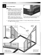
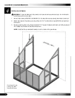
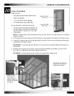
Secure front panels (#CG08100 & #CG08106) 

1.

to the base frame using 3/4" Phillips head 
screws.  Attach to the base frame using the 
corner brackets (1a) and the pre-installed 
brackets on the front panels (1b) as shown. 

NOTE:

  If needed, brace panels in place or 

have an assistant hold the panels steady until 
side panels can be attached to the front panels.

Secure panels together using the pre-installed 3" x 3" square brackets positioned over both panels and 

2.

3/4" Phillips head screws as shown.

2

Front Panel

3/4" Phillips 
head screws

Seat the panels into the corner brackets as shown 
and secure using 3/4" Phillips head screws.

FRONTBOARD

1a

Frame length of your 
building may differ 
from what is shown.

VER

TICAL

 W

ALL

CG08100

front panel

CG08106

front panel

Verify the 
pre-installed
brackets are 
to the inside.

2

View as seen 

from the inside.

Brackets come pre-
installed.  Secure using 
3/4" Philips head screws.

View as seen 

from the inside.

1b

Summary of Contents for 104900

Page 1: ...n date 06 18 09 2009 ClearSpan All Rights Reserved Reproduction is prohibited without permission STK DIMENSIONS 104900 8 W x 9 8 H x 17 3 L Ground Level Photo may show a model of a different length ClearSpan Home Attached Cedar Greenhouse ...

Page 2: ...ocation is an important step before you begin to assemble the structure Always consult local and regional building codes before you begin The following suggestions and precautions will help you determine whether your selected location is the best location Never erect the structure under power lines Identify whether underground cables and pipes are present before preparing the site or anchoring the...

Page 3: ...plied brackets and wedge anchors Consult the services of a qualified contractor for additional information and details Measure all lengths of plastic lumber and match them to the lumber lengths shown in the chart found below the base diagrams in the Quick Start section ASSEMBLY PROCEDURE Following the instructions as presented will help ensure the proper assembly of your greenhouse Failing to foll...

Page 4: ...wing procedure is a suggested method Its use depends on the size of the greenhouse the footings and the method used to anchor the shelter SQUARE THE SITE Identify a corner where a building rafter will be 1 positioned drive in a stake and string a line the exact width of the building and stake in place String a line at least as long as the building from the 2 first stake at 90 NOTE A transit can be...

Page 5: ...front back board one sideboard and a corner bracket 2 Assemble corner as shown below using 3 4 Phillips head screws FAF25P to secure Repeat at the remaining corners On the 3 outer sideboard attach pass thru connectors 104639 in the locations shown below Consult the Assembled Base View for the correct measurements and locations Use 3 4 Phillips head screws FAF25P to secure pass thru connectors Cons...

Page 6: ...sistant hold the panels steady until side panels can be attached to the front panels Secure panels together using the pre installed 3 x 3 square brackets positioned over both panels and 2 3 4 Phillips head screws as shown 2 Front Panel 3 4 Phillips head screws Seat the panels into the corner brackets as shown and secure using 3 4 Phillips head screws FRONTBOARD 1a Frame length of your building may...

Page 7: ...rs with the edge of the side panels as shown to the right and secure using 3 4 Phillips head screws Attach side panel to the front panel using three 2 1 2 construction screws FAS13 2 NOTE Construction screws are installed through the front panel and into the side panel as shown below View as seen from the outside 1 ATTENTION Verify that all pre installed brackets are to the inside of the greenhous...

Page 8: ...e as previously described in Section 2 1 Attach back panel to the side panel using three 3 2 1 2 construction screws FAS13 as described 2 in Section 3 Secure panels together using the pre installed 3 x 3 square brackets positioned over both panels and 3 3 4 Phillips head screws as described in Section 2 NOTE Verify that the pre installed brackets are to the inside of the greenhouse Frame length of...

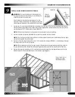
Page 9: ...s and one 1 12 top plate to the top of the side panels Measure and mark 25 1 2 from the end of the 2 top plate Continue measuring and marking in 25 1 2 increments for the on center middle rafter locations NOTE Mark the outside of the top plates and not the top This will allow the mark to be visible when the rafter assemblies are set into position FAS13 construction screws 1 2 25 1 2 Frame length o...

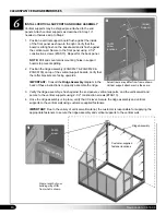
Page 10: ...rackets are facing upwards IMPORTANT Consult the Ridge Assembly diagram in the back of these instructions to properly assemble the ridge Verify the ridge assembly is flush against the end panels vertical supports and the vertical wall and 3 secure to the vertical supports using 2 1 2 construction screws FAS13 Once the ridge assembly is in place verify that it is level Secure the ridge assembly and...

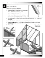
Page 11: ...ft of the vertical wall as seen from the front Locate finishing back panel CG72124 and remove two 2 pre installed 3 x 3 square brackets 1 from the side of the panel that will be toward the vertical wall NOTE These 3 x 3 square brackets are used to secure the panel to the outside of the greenhouse Install the back panel CG72124 as desired Secure panel using the two 2 pre installed 3 x 3 2 square br...

Page 12: ...ark on the top plate Using the pre drilled hole in the first step and 2 1 2 FAS13 construction screws secure the rafter leg to 3 the top plate Secure the rafter to the rafter brackets using 3 4 FAF25P Phillips head screws 4 Locate an A angle bracket 104642 and attach to the underside of the rafter leg as shown below 5 Secure using 3 4 FAF25P Phillips head screws Repeat steps for remaining rafters ...

Page 13: ... roof panel CG08118 and set it in position as shown below 2 NOTE The roof panel will be flush with the top of the adjacent rake board Additionally the top edge will be flush against the vertical wall Secure to the rake board using three 3 2 1 2 construction screws FAS13 3 Install screws through the rake board and into the roof panel NOTE When installed correctly the open edge of the double roof pa...

Page 14: ...back rake board secured into position secure the back roof panel to the rake board by 7 installing three 3 2 1 2 construction screws FAS13 through the side of the rake board and into the roof panel CG08121 Vented Panel CG08118 Double Panel 6 7 FAS13 screw locations Rake Board IMPORTANT Metal flashing is not supplied with greenhouse Due to the variety of vertical wall material the customer is respo...

Page 15: ...construction screws 2 Locate the remaining upper door panel and position the panel in the door opening and attach the hinges 3 as described in the previous step ATTENTION To ensure proper door operation a 1 4 gap must be maintained between the upper and lower panels With both door panels secured in place close each panel and attach door handles door lock and 2 4 turn button in the desired location...

Page 16: ...uded with the solar vent opener to assemble the vent before attaching it to the greenhouse After the vent opener is assembled continue with the these instructions Verify that the vent panel on the greenhouse opens easily and is unobstructed 1 Choose one of the assembled solar vent openers and attach it to the greenhouse frame and the vent 2 panel as shown in the diagram Secure using 1 1 8 FAS8 con...

Page 17: ...emove debris and objects that may accumulate on the shelter Use tools that will not damage the panels when removing debris Remove snow to prevent excess accumulation Use tools that will not damage the shelter when removing snow Never allow snow to accumulate on the roof or against the lower panels Check the contents of the shelter to verify that nothing is touching the panels that could cause dama...

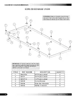
Page 18: ...tor 3 6 104643 Middle Connector 8 EXPLODED BASE VIEW 3 6 2 6 1 6 6 3 6 6 2 5 5 5 2 6 2 1 4 4 6 4 4 ATTENTION Measure all lengths of plastic lumber and match them to the lumber lengths shown in the chart below to verify that you have the correct parts ATTENTION For concrete surfaces anchor the frame using customer supplied brackets and wedge anchors Consult the services of a qualified contractor fo...

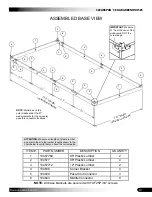
Page 19: ...ons IMPORTANT Measure 51 from the ends of the sideboards NOT the corner edge ATTENTION Measure all lengths of plastic lumber and match them to the lumber lengths shown in the chart below to verify that you have the correct parts NOTE All base brackets are secured with FAF25P 3 4 screws ITEM PART NUMBER DESCRIPTION QUANTITY 1 10457769 95 Plastic Lumber 2 2 104577 96 Plastic Lumber 4 3 10457712 12 P...

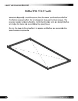
Page 20: ...me point as shown below The frame is square when the two diagonal measurements are equal The recycled plastic lumber is flexible Verify that the side rails are straight before anchoring the base and assembling the greenhouse Anchor the base to the site after it is square and before you assemble the greenhouse components ...

Page 21: ...Level Install ground anchors before attaching greenhouse panels and after base frame is square Secure anchors to base frame after greenhouse panels are installed and check frame for square ATTENTION For concrete surfaces anchor the frame using customer supplied brackets and wedge anchors Consult the services of a qualified contractor for additional information and details ...

Page 22: ... 2 13 1 2 25 1 2 6 25 1 2 25 1 2 25 1 2 CG08127 CG08129 CG08130 105122 105122 105122 105122 105122 105122 105122 104637 104637 NOTE Secure all brackets with FAF25P screws CG08129 CG08130 CG08127 Secure CG08127 and CG08129 and CG08130 with a 104643 bracket using FAF25P 3 4 screws FRONT VIEW BACK VIEW ...

Page 23: ...23 CLEARSPAN CEDAR GREENHOUSES Revision date 06 18 09 Space below is reserved for customer notes ...

Reviews: