background image

CLEARSPAN

 VALUE LINE

12

Revision date: 10.05.10

CABLE ASSEMBLY

Cable assemblies provide diagonal bracing for the building.  

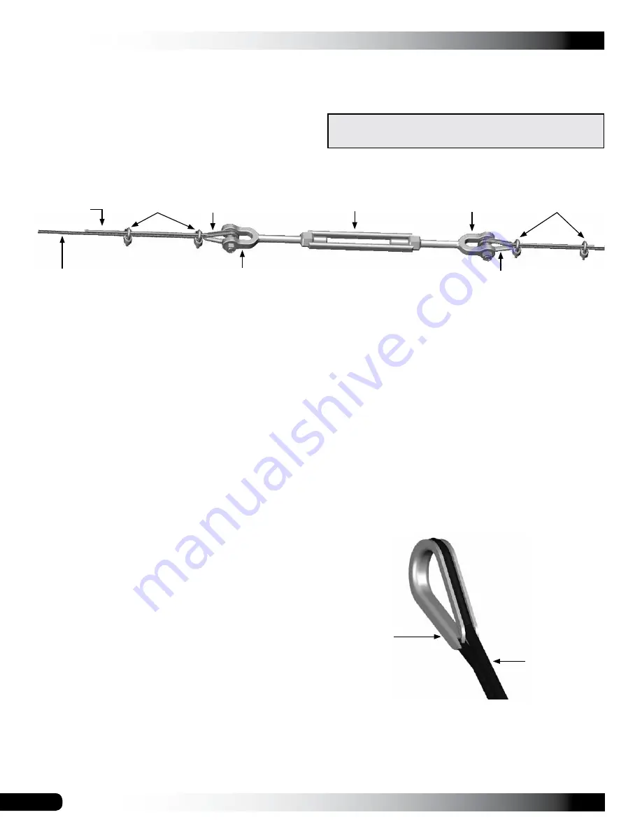
Each cable assembly includes the following items:
•  Cable (2 cables cut to length)
•  Turnbuckle (1)
•  Cable thimbles (4)
•  Cable clamps (4) 

NOTE: 

For each cable assembly, four (4) additional cable clamps are used to attach the cable assembly to the frame. 

In addition, Cable C assemblies require an additional cable thimble at each lower end to complete the connection to the 

band clamp attached to the rafter leg. See Side Profile Diagrams. Consult the Cable Diagram on the following page and 

the Side Profile Diagram in the Quick Start section for clarification and cable locations.

Cable Assembly Procedure
1.  Using the Side Profile Diagram in the Quick Start section (and others) as guides, measure the distance needed on 

the frame and cut the cable to the proper length for each assembly. Remember to account for the turnbuckle and the 

cable length needed to attach the thimbles at each end. (Extra cable has been sent for the cabling.) Make a single 

assembly 

before

 making them all. This allows a check to be sure the correct length has been cut. Make the necessary 

length adjustments as needed before making additional assemblies. 

Always measure before cutting the cable. 


ATTENTION:

 One (1) turnbuckle and two (2) cables are used for each cable assembly type. For best results and 

the least cable waste, use the diagram on the following page and measure the distance required for a specific cable. 

Additional cable length is needed to anchor the cable to the frame and to attach the cable sections to the turnbuckle.  


Measure and cut the follow assemblies as needed:

2.  Place one cable thimble approximately twelve inches 

(12") from the end of a cable section and wrap the 

cable around the thimble as shown in the figure to the 

right.

3.  Grasp both sections of the cable near the thimble 

and position one cable clamp one inch away from the 

thimble as shown above. 


NOTE:

 Position the clamp on the cable with its U-bolt 

portion over the short/"dead" cable section.

4.  With the saddle portion of the cable clamp in position 

on the "live" cable section, thread the nuts onto the U-

bolt section of the clamp and tighten slightly to maintain 

the position of the clamp on the cable.

Thimble

Cable

•  Cable Assembly A: 16 cable lengths; 8 turnbuckles
•  Cable Assembly B: 16 cable lengths; 8 turnbuckles
•  Cable Assembly C: 16 cable lengths; 8 turnbuckles

ATTENTION: 

Consult the diagram on the next page to 

identify cable assemblies and cable locations.

Cable Clamps

Thimble

"Live" Cable 

Section

Turnbuckle

Turnbuckle Jaw

Thimble

Turnbuckle Jaw

Cable Clamps

Typical Turnbuckle Assembly

"Dead" Cable 

Section

Summary of Contents for 106181

Page 1: ...2010 ClearSpan All Rights Reserved Reproduction is prohibited without permission ClearSpan 30 Wide Heavy Duty Round Style Storage Master Photo may show a model of a different length STK DIMENSIONS 106181 30 W x 11 H x 30 L 106182 30 W x 11 H x 40 L ...

Page 2: ...Failing to anchor the shelter properly will void the manufacturer s warranty and may cause serious injury and damage LOCATION Choosing the proper location is an important step before you begin to assemble the structure The following suggestions and precautions will help you determine whether your selected location is the best location Never erect the structure under power lines Identify whether un...

Page 3: ...fore you begin to assemble your shelter Conduit An assembly of pipes used to secure the main cover and end panels if equipped Purlins and some strut assemblies also consist of connected pipes to form a conduit Each pipe joint of a conduit assembly is secured with a self tapping Tek screw Coupler or Fitting A part of the frame assembly where legs purlins and rafter pipes are inserted and secured In...

Page 4: ...sult the Pictorial Parts Guide and all shelter diagrams throughout these instructions for clarification or contact Customer Service NOTE At this time you do not need to open the plastic bags containing the fasteners if used QUICK START GUIDE For a quick overview of this shelter and its components consult the Quick Start Guide near the back of these instructions The pages of the Quick Start Guide s...

Page 5: ...ional details and diagrams All parts are not shown FA4482B Tek Screw QH1061 1 Ratchet 100441 Nut Setter Swaged Plain Swaged and Plain Rafter Sections not all pieces are shown QH1065 2 Ratchet AS1003 3 16 Cable Clamp AS1083 3 16 Cable Thimble 104189 Turnbuckle 102546 Cross Connector QH1070 Pipe Strap 103856 Band Clamp FAH325B FALB32B Carriage Bolt Nut 104302 Pipe Fitting w Plate ...

Page 6: ...he required parts for each assembly procedure 2 Assemble all rafters 3 Assemble and anchor the frame 4 Cut assemble and install all cables 5 Install end panels 6 Prepare and install the main cover The instructions that follow describe assembling all rafters and then constructing the frame Depending on the number of individuals assisting with the construction it may be best and more efficient to ha...

Page 7: ...les of 3 4 5 such as 6 8 10 or 12 16 20 helps to maintain an accurate 90 angle 3 After squaring the position of the building and placing a stake at all corners string a line between the stakes to mark the base of the building 4 Next paint or mark a line on the ground using the strings between the stakes as guides Space below is reserved for customer notes NOTE If a baseboard is used drill holes th...

Page 8: ...fter using two 2 Tek screws for each strap Attach the brackets to the underside of the rafter in the locations shown below and on the Front Profile diagram in the Quick Start section at the back of these instructions The QH1070 straps should remain loose do not fully tighten at this time 4 Move to the end of each rafter leg and slide one 1 103856 band clamp onto each leg 5 Attach a ratchet QH1065 ...

Page 9: ...ver damage when it is installed 3 Repeat the steps to assemble the remaining interior rafters that include QH1065 ratchets Consult the Side Profile Diagram in the Quick Start Guide near the back of these instructions to view the position and number of interior rafters with ratchets Do not use the QH1061 ratchets during this procedure use only the remaining QH1065 ratchets 29R23S1D 29R23S1D 104302 ...

Page 10: ... Repeat the above procedure to assemble the remaining interior rafters without ratchets 5 Place all interior rafters without attached ratchets in a pile separate from either of the other rafter piles NOTE You must be able to access all three rafter piles easily throughout the assembly steps Forklifts and personnel booms are recommended for lifting and setting the rafters Consult a construction pro...

Page 11: ...pacing between the end rafter and the first interior rafter is on center and install the first section of purlin pipe at this location Verify that rafters are plumb 11 Move to the other side of the rafter and repeat Step 10 12 Install the first pipe section of remaining purlins There are nine 9 purlins between each rafter Consult the Frame Diagram shown earlier in these instructions for purlin loc...

Page 12: ...s Always measure before cutting the cable ATTENTION One 1 turnbuckle and two 2 cables are used for each cable assembly type For best results and the least cable waste use the diagram on the following page and measure the distance required for a specific cable Additional cable length is needed to anchor the cable to the frame and to attach the cable sections to the turnbuckle Measure and cut the fo...

Page 13: ...wrapped and secured See the insert in the diagram below for Steps 11 and 12 12 Insert the 5 16 x 5 carriage bolt FAH325B down through the 5 16 hole add a 5 16 nut and tighten 13 Repeat Steps 11 and 12 for the remaining rafter purlin position at the other end of the frame 14 Attach the cables to the assembled frame See the diagrams below and in the Quick Start section of these instructions for deta...

Page 14: ...rofile Diagram in the Quick Start section for rafter spacing and cable locations View is from inside the shelter Carriage bolt runs through rafter and top center purlin on the 3rd rafter at each end View is from inside the shelter Attach the band clamp 103856 above the lowest pipe strap QH1070 on the end rafters only Once the cable is attached and the clamp is tightened secure the clamp to the raf...

Page 15: ...72 pipe Two 2 end conduits are required 2 Assemble an end conduit by connecting four 4 swaged pipes and one 1 plain pipe 3 Secure the joints using Tek screws and tape over the Tek screws to protect the end panel 4 Repeat assembly for the remaining end conduit ANCHOR THE SHELTER After installing all cable assemblies anchor the frame Once the frame is anchored properly continue with these instructio...

Page 16: ...rough the door sections End Conduit through Side Panel End Conduit through Side Panel 3 Slide the remaining end conduit assembly into the hem at the bottom of the solid plain end panel 4 Continue with the next procedure ATTACH END CONDUIT ASSEMBLIES 1 Using two 2 QH1330 angled brackets secure one 1 angled bracket to each end of the end conduit and secure the conduit to the legs of the end rafter S...

Page 17: ... clip and the Tek screw in a location that will not contact the main cover when it is installed Actual number of clips may differ from what is shown in the diagram that follows The end panel may be shipped as an untrimmed rectangular piece If desired use scissors or other means to trim the excess end panel material that remains after the panel is attached 5 Repeat Steps 1 4 to pull the remaining e...

Page 18: ...th of the frame This cover conduit is identical to the on center length of the shelter Once assembled insert the cover conduits into the side pockets of the main cover The conduits are used to tighten and secure the main cover to the frame Consult the Side Profile Diagram in the Quick Start section for pipe identification 2 After assembling the cover conduits locate the main cover and unfold it on...

Page 19: ...nside of the building This will be the underside of the cover when it is pulled into position on the frame NOTE Use lifts and additional assistants if needed to help pull the cover up and over the frame Shelter shown above may be a different length Cover Conduit Ropes 4 Once the main cover is pulled into position center the cover on the frame and remove the ropes Loosely secure the ends of the cov...

Page 20: ... the same NOTE If ropes were used at these locations when the main cover was pulled in place a slit in the cover pocket may already be present When creating the slit in the pocket for the strap do not cut the main cover Cut only the pocket material 2 Select one of the tie down straps CC5391 that shipped with the building and insert one end of the strap through the slit and around the cover conduit...

Page 21: ...ents are tight and in good repair Inspect all building components regularly Replace all worn or damaged parts promptly If the shelter is moved inspect all parts and connections before reassembling For replacement or missing parts call 1 800 245 9881 for assistance NOTE With the exception of Truss Arch buildings ClearSpan shelters and greenhouses do not have any tested loading criteria TIGHTEN THE ...

Page 22: ...CLEARSPAN VALUE LINE 22 Revision date 10 05 10 Frame shown may differ in length from actual frame QUICK START GUIDE 30 Wide Heavy Duty Round Style Building ...

Page 23: ...the underside of the rafter as shown To space the straps identify the top center position and work down to each rafter foot There are 9 QH1070 pipe straps for each end rafter Assemble the end rafters identically to keep the purlins running parallel to each other throughout the length of the frame Consult the frame assembly steps for additional details Top Center Purlin Location Ground Level ...

Page 24: ...CLEARSPAN VALUE LINE 24 Revision date 10 05 10 SIDE PROFILE 106181 5 16 x 5 Carriage Bolt Location Band Clamp Band Clamp Band Clamp Band Clamp ...

Page 25: ...25 CLEARSPAN VALUE LINE Revision date 10 05 10 SIDE PROFILE 106182 5 16 x 5 Carriage Bolt Location Band Clamp Band Clamp Band Clamp ...

Page 26: ...CLEARSPAN VALUE LINE 26 Revision date 10 05 10 CONNECTIONS Frame shown may differ in length from actual frame ...

Page 27: ...27 CLEARSPAN VALUE LINE Revision date 10 05 10 CONNECTION DETAILS ...

Reviews: