15
CLEARSPAN
™
VALUE LINE
Revision date: 10.05.10
TIGHTEN THE CABLING
The positions of the cable assemblies are identical for the
opposite side and the remaining end of the building that are
not shown in the previous diagram. For cable locations for
your building, consult the Quick Start section (back).
1. After attaching all cable assemblies to the building
frame, verify that each band clamp is tight and secured
to the rafter leg using a Tek screw.
2. Return to the first set of turnbuckles and tighten the
cables.
NOTE:
Tighten the cables in each section evenly so
that the frame remains plumb.
3. After one set of cables is tightened, move to another
set and repeat the steps to tighten those cables.
4. Repeat this process until all cables are tight.
END CONDUITS ASSEMBLY
The end conduits are assembled and the end panels are
installed after the frame is anchored and the cables have
been tighten. The following steps describe one way to
assemble the end conduits and prepare the end panels.
Gather the Parts:
• Pipe 1.315'' x 75'' swaged
• Pipe 1.315'' x 72'' plain
• Duct tape and Metal cutting saw
• Tek screws
Assembly Procedure:
1. Locate the end conduit pipes. Each end conduit
consists of four (4) 75” pipe and one (1) 72” pipe. Two
(2) end conduits are required.
2. Assemble an end conduit by connecting four (4)
swaged pipes and one (1) plain pipe.
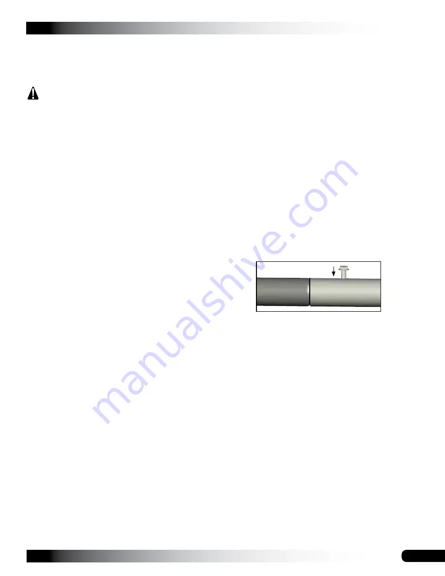
3. Secure the joints using Tek screws and tape over the
Tek screws to protect the end panel.
4. Repeat assembly for the remaining end conduit.
ANCHOR THE SHELTER
After installing all cable assemblies, anchor the frame.
Once the frame is anchored properly, continue with these
instructions.
WARNING
: Securing the rafter mounting feet to
baseboards set on the site is not a substitute for
properly anchoring the shelter. You must anchor the
shelter as described in the MUST READ document.
FAILING TO PROPERLY ANCHOR THE SHELTER
WILL RESULT IN DAMAGE TO THE SHELTER AND
MAY CAUSE PERSONAL INJURY.
READ THE MUST READ DOCUMENT TO PROPERLY
ANCHOR THE SHELTER.
FINAL FRAME CHECK
1. Return to the frame connections and verify that all bolts
are tight.
2. Verify that each purlin splice is secured with a Tek
screw.
3. Verify that each purlin is secured to the cross connector
and that each cross connector is secured to the rafter
pipe. See Page 11 if needed.
4. Inspect the frame for any sharp areas that could
damage the cover. If found, reposition components or
tape with layers of duct tape.
5. Verify that all bolts are positioned with the heads to the
outside of the frame. Tape the bolts, rafter joints, and
cable connections
before
installing the cover.
6. Continue with assembling the end conduits.


