CLEARSPAN
™
POLY BUILDINGS
16
Revision date: 12.08.15
CABLE ASSEMBLY
Cable assemblies provide diagonal bracing.
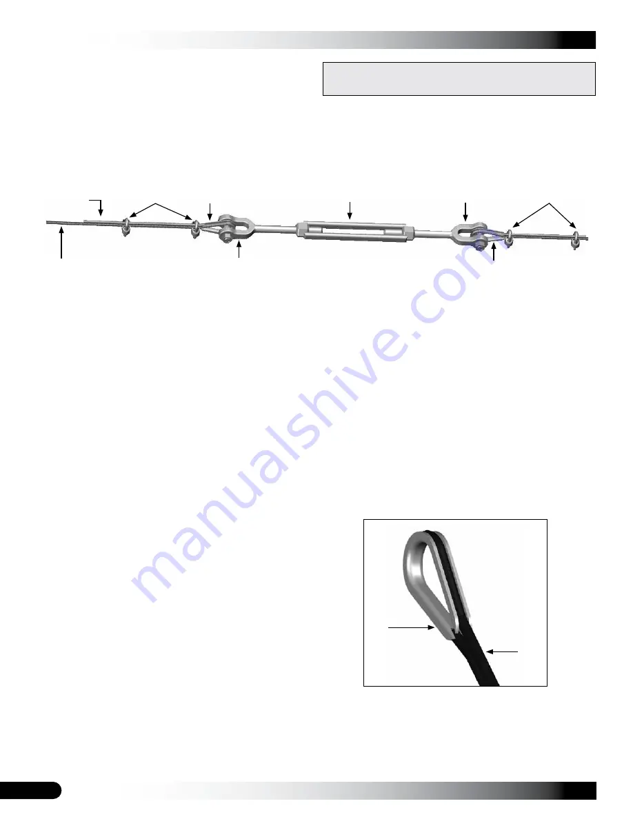
Each cable assembly includes the following items:
• Cable (2 cables cut to length)
• Turnbuckle (1)
• Cable thimbles (4)
• Cable clamps (4)
NOTE:
For each cable assembly, four (4) additional cable clamps are used to attach cable assembly to frame. In
addition, Cable C assemblies require an additional cable thimble at each lower end to complete the connection to
band clamp attached to end rafter leg. See Side Profile Diagrams. Consult Cable Diagram on following page and Side
Profile diagram in Quick Start section for clarification and cable locations.
Cable Assembly Procedure
1. Using the Side Profile Diagram in Quick Start section as a guide, measure distance needed on frame and cut
cable to the proper length for each assembly. Remember to account for the turnbuckle and the cable length
needed to attach thimbles at each end. (Extra cable has been sent for cabling.) Make a single assembly
before
making them all. This allows a check to be sure the correct length has been cut. Make the necessary length
adjustments as needed before making additional assemblies. To prevent running out of cable,
always measure
before cutting.
ATTENTION:
One (1) turnbuckle and two (2) cables are used for each cable assembly type. For best results and
to reduce cable waste, use the diagram on the next page and measure the distance required for a specific cable
type. Additional cable length is needed to anchor cable to frame and to attach cable sections to turnbuckle.
Measure and cut the follow assemblies as needed:
2. Place one cable thimble approximately twelve inches (12")
from end of a cable section and wrap cable around thimble
as shown in the figure to the right.
3. Grasp both sections of the cable near the thimble and
position one cable clamp one inch away from thimble as
shown above.
NOTE:
Position clamp on cable with its U-bolt portion over
the short/"dead" cable section.
4. With the saddle portion of the cable clamp in position on
the "live" cable section, thread nuts onto U-bolt section of
clamp and tighten slightly to maintain clamp position.
Thimble
Cable
• Cable Assembly A: 16 cable lengths; 8 turnbuckles
• Cable Assembly B: 16 cable lengths; 8 turnbuckles
• Cable Assembly C: 16 cable lengths; 8 turnbuckles
ATTENTION:
Consult the diagram on the next page to
identify cable assemblies and cable locations.
Cable Clamps
Thimble
"Live" Cable
Section
Turnbuckle
Turnbuckle Jaw
Thimble
Turnbuckle Jaw
Cable Clamps
Typical Turnbuckle Assembly
"Dead" Cable
Section


