Maintenance
5-2
750-297
Profire E/LNE Series Manual
5.2.1 — Programming Control
This control requires no adjustment, nor should any attempt be made to alter contact settings or timing logic. Those
programmers with contacts may require occasional cleaning. If so, follow instructions given in the manufacturer's
bulletin. Never use abrasive materials. The manufacturer's bulletin also contains troubleshooting information. The
flame detector lens should be cleaned as often as conditions demand. A periodic safety check procedure should be
established to test the complete safeguard system. Tests should verify safety shutdown with a safety lock out upon
failure to ignite the pilot or the main flame, and upon loss of flame. Each of these conditions should be checked on a
scheduled basis. The safety check procedures are contained in the manufacturer's bulletin.
5.3 — Impeller and Inlet Cone
Proper clearance between the impeller and the inlet housing set at 3/8” nominal. Adjust the inlet cone so it is centered
in the inlet of the impeller and tighten the bolts. There should be no contact between the inlet cone and the impeller.
Inserting a bar through the impeller blade and using it as a lever will only damage the blade and also void the impeller
warranty.
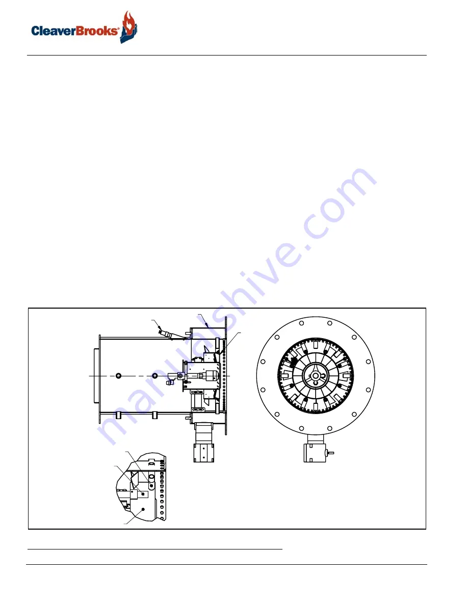
5.4 — Firing Head Inspection
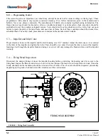
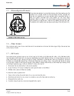
Disconnect the damper linkage, release the impeller housing latches, and swing the housing open for access to the
firing head. Inspect the flame scanner lens to be sure it is clean Inspect the lead wire to the ignition electrode. It must be
firmly attached and the insulation should be clean and free of cracks. The oil nozzle should be inspected periodically
depending on the grade of oil burned and the cleanliness of the environment.
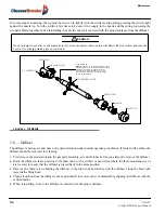
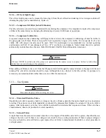
FIGURE 5-1.
Firing Head Assembly
PILOT
DIFFUSER
GAS SPUD
GAS MANIFOLD
SCANNER
DIFFUSER
FIRING HEAD ASSEMBLY

