background image

Chapter 2 — Burner Operation and Control

Part No. 750-184

2-5

subsequent setting of fuel input throughout the firing range. It 
has no control over the firing rate when the manual-automatic 
switch is set on “automatic.”

11.Burner Switch (Figure 2-8): A manually operated start-stop 

switch for directly starting and stopping operation of burner.

12.Flame Detector: Monitors gas or oil pilot and energizes the 

programmer flame relay in response to a flame signal. It 
continues to monitor main flame (oil or gas) after expiration of 
pilot providing period. A standard equipped boiler has a lead 
sulfide (infrared sensitive) detector.

13.Combustion Air Proving Switch: A pressure-sensitive switch 

actuated by air pressure from the forced draft fan. Its contacts 
close to prove presence of combustion air. The fuel valves cannot 
be energized unless this switch is satisfied. The combustion air 
proving switch is provided on all gas fired or combination gas-oil 
burners. An oil fired boiler does not normally have a separate 
switch but utilizes the atomizing air proving switch to the same 
effect, since the presence of atomizing air from the air pump, 
which is belt driven from the blower motor, is evidence of blower 
operation.

14.Alarm: Sounds to notify the operator of a condition requiring 

attention. The alarm is available as optional equipment.

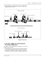
15.Stack Thermometer (Figure 2-6): Indicates temperature of 

vented flue gases.

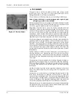
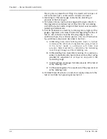
16.Diffuser (Figure 2-7): A circular plate, located at the furnace end 

of the burner drawer, that imparts a rotary swirling motion to 
combustion air immediately prior to its entering the flame, thus 
providing a thorough and efficient mixture with the fuel.

17.Rotary Air Damper (Figure 2-7): Provides accurate control of 

combustion air in proportion to fuel input for various load 
demands. It consists of two concentric cylinders with openings. 
The outer is stationary. The inner is rotated, under control of the 
modulating motor, to vary the effective size of the openings 
where they overlap.

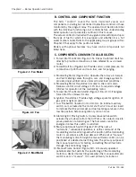
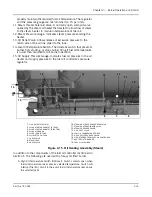
18.Indicator Lights (Figure 2-8): Provide visual information of boiler 

operation as follows (indicator lights vary with controls 
provided):

• Flame Failure
• Load  Demand 
• Fuel Valve (valve open)
• Low Water

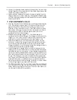
Figure 2-6  Stack Thermometer

Figure 2-7  Diffuser & Damper

Diffuser

Rotary Air
Damper

Figure 2-8  Control Panel

Summary of Contents for CB Ohio Special 100 HP

Page 1: ...Model CB LE Packaged Boiler 125 200 HP Operation Service and Parts Manual 750 184 04 09 and Model CB Ohio Special 125 225 HP ...

Page 2: ...ii ...

Page 3: ...nuals to your local Cleaver Brooks authorized representative Manual Part No 750 184 04 09 Printed in U S A Cleaver Brooks 2009 CLEAVER BROOKS Model CB LE Packaged Boiler 125 200 HP Light Oil Heavy Oil Gas or Combination Operation Service and Parts Manual ...

Page 4: ...how how a basic burner operates Operating controls will normally function for long periods of time and we have found that some operators become lax in their daily or monthly testing assuming that normal operation will continue indefinitely Malfunctions of controls lead to uneconomical operation and damage and in most cases these conditions can be traced directly to carelessness and deficiencies in...

Page 5: ...NSPECTION 3 15 I PREPARATION FOR EXTENDED LAY UP 3 16 Chapter 4 Sequence Of Operation A GENERAL 4 2 B CIRCUIT AND INTERLOCK CONTROLS 4 2 C SEQUENCE OF OPERATION OIL OR GAS 4 4 D FLAME LOSS SEQUENCE 4 6 Chapter 5 Starting And Operating Instructions A GENERAL PREPARATION FOR START UP ALL FUELS 5 2 B CONTROL SETTINGS STEAM AND HOT WATER 5 3 C GAS PILOT 5 4 D ATOMIZING AIR 5 4 E FIRING PREPARATIONS FO...

Page 6: ...TER THERMOSTAT 400 and 600 Series Steam 6 24 BB STEAM OIL HEATER THERMOSTAT No 6 Oil 400 and 600 Series Steam 6 24 CC HOT WATER OIL HEATER THERMOSTAT 400 and 600 Series 6 24 DD STEAM HEATER PRESSURE REGULATOR 400 and 600 Series Steam 6 25 Chapter 7 Troubleshooting 7 1 Chapter 8 Inspection And Maintenance A GENERAL 8 2 B FIRESIDE CLEANING 8 3 C WATER LEVEL CONTROLS 8 4 D WATER GAUGE GLASS 8 5 E ELE...

Page 7: ...2 Front Head Electrical CB LE 9 23 Front Head Electrical CB OS 9 25 Straight Electric Oil Heater 60 Heavy Oil 9 27 Heavy Oil Piping 60 Steam 9 29 Common Oil Parts Heavy Oil 9 31 Side Mounted Air Compressor Piping 9 32 Air Compressor Piping CB OS 9 33 Air Line Piping 9 34 Light Oil Piping 9 35 Light Oil Air Piping Front Head 9 36 Pilot Gas Train 125 150HP CB LE 125 175HP CB OS 9 38 Pilot Gas Train ...

Page 8: ...viii ...

Page 9: ... cleaver brooks com Chapter 1 Basics of Firetube Operation A GENERAL 1 2 B THE BOILER 1 4 C CONSTRUCTION 1 5 D STEAM CONTROLS ALL FUELS 1 7 E HOT WATER CONTROLS ALL FUELS 1 8 F IFGR COMPONENTS CB LE 1 9 G CB OHIO SPECIAL 1 11 ...

Page 10: ...rs serve to redirect the combustion gasses through the various firetube passages The flame originates in the furnace As the combustion gasses travel down the furnace and through the various firetube channels heat from the flame and combustion gasses is transferred to the water Transferred energy develops into the required steam or hot water The primary purpose of the boiler is to supply energy to ...

Page 11: ...o all grades of heavy oil The LE option reduces Nitrogen Oxide NOx emissions a major precursor to ozone pollution smog Carbon Monoxide CO emissions also tend to be lower due to increased turbulence caused by the addition of the flue gases into the combustion air stream thereby improving combustion Notice For information on IFGR when firing heavy oil review the Operation and Maintenance manual for ...

Page 12: ...diction are to be consulted permits obtained etc All boilers in the above series comply when equipped with optional equipment to Industrial Risk Insurers IRI Factory Mutual FM or other insuring underwriters requirements B THE BOILER The Model CB CB LE boiler is a packaged firetube boiler of welded steel construction and consists of a pressure vessel burner burner controls forced draft fan damper a...

Page 13: ...ipment damage Feedwater equipment should be checked and ready for use Be sure that all valves piping boiler feed pumps and receivers are installed in accordance with prevailing codes and practices Water requirements for both steam and hot water boilers are essential to boiler life and length of service Constant attention to water requirements will pay dividends in the form of longer life less down...

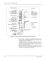
Page 14: ... 1 2 3 4 5 6 7 8 9 10 11 12 13 14 1 Forced draft fan motor 2 Oil pressure gauge 3 Atomizing air pressure gauge 4 Modulating motor 5 Gas Train not shown 6 Fuel oil controller 7 Ignition transformer 8 Oil strainer 9 Air compressor 10 C B Level Master controls 11 Low Water Cut Off Pump Control 12 Vent Valve 13 Limit Controls 14 Control Panel ...

Page 15: ...iler It performs two distinct functions Stops firing of the burner if water level lowers below the safe operating point Energizes the low water light in the control panel also causes low water alarm bell optional equipment to ring Code requirements of some models require a manual reset type of low water cutoff Starts and stops the feedwater pump if used to maintain water at the proper operating le...

Page 16: ...stalling a flange connected valve use a new gasket and draw the mounting bolts down evenly Do not install or remove side outlet valves by using a pipe or wrench in the outlet Warning Only properly certified personnel such as the safety valve manufacturer s certified representative can adjust or repair the boiler safety valves Failure to follow these instructions could result in serious personal in...

Page 17: ...everal arms driven from the jackshaft to provide modulating control see Figure 1 16 3 Over Travel Mechanism The over travel mechanism has two functions It allows the linkage to pass through the front door and it allows jackshaft rotation to exceed over travel IFGR linkage movement A set of springs allows the linkage to stay in a fixed position while the jackshaft rotates 4 Fuel Change Over Linkage...

Page 18: ...e to control temperature build up The insulation is held in place with wire mesh Figure 1 6 Induced Flue Gas Recirculation System General Arrangement COMBUSTION AIR INLET FRONT DOOR CASSETTE MOUNTING BOLTS AIRBOX GASKET CASSETTE LIFTING EYES FAN MOTOR CASSETTE FLANGE COLLAR COMBUSTION AIR FAN OVER TRAVEL MECHANISM IFGR DAMPER LINKAGE QUICK DISCONNECT LINKAGE JACKSHAFT ARM BURNER DRAWER BURNER DRAW...

Page 19: ...ually to CB LE and CB OS models Two Pass Design The principal difference between the Ohio boilers and CB LE boilers in the corresponding size range is the construction of the pressure vessel Ohio Special boilers identified by an S suffixed to the model number are of a two pass design as opposed to the four pass design of the CB LE Rear Head Due to the two pass design of the Ohio boiler the rear he...

Page 20: ...ctions as outlined in Section 8 of this manual Front Head The Ohio Boiler utilizes an insulated inner intermediate front door Due to the two pass design the front head lacks the second to third pass baffle found on comparable CB LE boilers See Section 8 for front head sealing procedure Dimpled Tubes The second pass tubes are 2 O D and of dimpled design for increased heat transfer ...

Page 21: ...ALL BOILERS 2 4 D CONTROLS FOR GAS FIRING 2 6 E CONTROLS COMMON TO OIL FIRED BOILERS INCL COMB 2 7 F ADDITIONAL CONTROLS FOR HEAVY OIL 2 12 G CONTROLS FOR COMBINATION BURNERS ONLY 2 14 H COMBUSTION AIR 2 14 I AUTOMATIC IGNITION 2 15 J ATOMIZING AIR 2 15 K OIL FUEL FLOW LIGHT OIL 2 16 L OIL FUEL FLOW HEAVY OIL 2 18 M GAS FUEL FLOW 2 20 N MODULATING FIRING 2 20 ...

Page 22: ...d main flame and a period of continued blower operation to postpurge the boiler of all unburned fuel vapor Other safety controls shut down the burner under low water conditions excess steam pressure or water temperature Safety interlock controls include combustion and atomizing air proving switches and depending upon the fuel and insurance carrier requirements controls that prove the presence of a...

Page 23: ...ion to the standard basic controls supplied other devices may be required to meet specific requirements of an insurance carrier or local code Refer to the Wiring Diagram WD prepared by Cleaver Brooks for your specific installation to determine the specific controls in the burner and limit control circuits Figure 2 2 Controls Components Common to All Boilers 1 2 3 4 5 6 7 8 9 10 1 Forced draft fan ...

Page 24: ...rcuit voltage 115 Vac to required voltage 24Vac for operation of the modulating motor 5 Forced Draft Fan Motor Starter Figure 2 9 2 10 Energizes forced draft fan blower motor 6 Ignition Transformer Provides high voltage spark for ignition of gas pilot or light oil pilot 7 Low Fire Switch located in mod motor An internal auxiliary switch cam actuated by the motor shaft which must be closed to indic...

Page 25: ...proving switch to the same effect since the presence of atomizing air from the air pump which is belt driven from the blower motor is evidence of blower operation 14 Alarm Sounds to notify the operator of a condition requiring attention The alarm is available as optional equipment 15 Stack Thermometer Figure 2 6 Indicates temperature of vented flue gases 16 Diffuser Figure 2 7 A circular plate loc...

Page 26: ...lot Shutoff Cock For manually opening or closing the gas supply to gas pilot valve 3 Gas Pressure Gauge Indicates gas pressure to pilot 4 Gas Pressure Regulating Valve Reduces incoming gas pressure to suit the pilot 5 Main Gas Cock For manually opening and closing the main fuel gas supply downstream of the main gas line pressure regulator A second shutoff cock downstream of the main gas valve s is...

Page 27: ...licable to all oil fired or gas and oil fired boilers 1 Oil Drawer Switch Opens the limit circuit if oil drawer burner gun is not latched in the forward position required for burning oil 2 Atomizing Air Proving Switch Pressure actuated switch whose contacts are closed when sufficient atomizing air pressure from Figure 2 9 Gas Train Shut Off Valve Low Gas Pressure Switch Main Gas Valve Gas Valve w ...

Page 28: ...ts In addition to these the controller used on a No 6 oil fired burner has additional components described in Section I A Oil Metering Valve Valve metering stem moves to increase or decrease the orifice area to regulate the supply of fuel oil to the burner nozzle in accordance with boiler load variances Stem movement is controlled by the modulating motor through linkage and the oil metering cam B ...

Page 29: ...rt No 750 184 2 9 Figure 2 10 Components Common to Oil Fired Boilers 6 5 7 3 4 1 2 1 OIL DRAWER SWITCH 2 ATOMIZING AIR PROVING SWITCH 3 ATOMIZING AIR PRESSURE GAUGE 4 OIL SOLENOID VALVE 5 FUEL OIL CONTROLLER 6 OIL RELIEF VALVE 7 TERMINAL BLOCK ...

Page 30: ...ING VALVE OIL PRESSURE REGULATOR OIL SUPPLY OIL RETURN TO MAIN OIL SOLENOID VALVE GLAND OIL BURNER PRESSURE GAUGE BACK PRESSURE ORIFICE OIL MODULATING CAM OIL METERING VALVE PACKING GLAND OIL PRESSURE REGULATOR OIL RETURN PRESSURE GAUGE FUEL OIL THERMOMETER OIL RETURN OIL SUPPLY MANUAL BY PASS VALVE BACK PRESSURE VALVE TO MAIN OIL ORIFICED VALVE OIL BURNER SOLENOID VALVE PRESSURE GAUGE ...

Page 31: ...cally by the programmer s sequence It includes components described A H A Air Pump Motor Drives the air pump and an air cooling fan The motor is started and stopped simultaneously with the forced draft fan motor B Air Pump Provides air for atomization of the fuel oil C Air Filter The filter cleans the air supply prior to entering air pump D Check Valve Prevents lubricating oil and compressed air f...

Page 32: ...ded boiler lay up or at any time the fuel oil transfer pump is stopped 2 Electric Oil Heater Thermostat Senses fuel oil temperature and energizes or deenergizes the electric oil heater to maintain required temperature of the fuel oil 3 Steam Oil Heater Thermostat Senses fuel oil temperature and controls the opening and closing of the steam heater valve to maintain the required temperature of the f...

Page 33: ...ssure in the oil heater and supply pressure to the fuel oil controller s pressure regulator In addition to the components of the fuel oil controller mentioned in Section E the following are used with a heavy oil fired burner A High Oil Temperature Switch Optional Switch contacts open when fuel oil temperature raises above a selected temperature Switch will interrupt the limit circuit in the event ...

Page 34: ...er I Air Purge Valve Solenoid valve opens simultaneously with closing of oil solenoid valve at burner shutdown allowing compressed air to purge oil from the burner nozzle and adjacent piping The oil is burned by the diminishing flame which continues burning for approximately 4 seconds after the oil solenoid valve closes J Air Purge Orifice Nozzle Limits purging air to proper quantity for expelling...

Page 35: ...he utility s main or from a tank bottle supply Secondary air flows into and mixes with the pilot gas stream to provide an adequate flame Insurance regulations may require two gas pilot solenoid valves with a normally open vent valve between them The vent valve closes when the gas pilot valves open and opens when the gas pilot valves shut to vent gas should any be present in the pilot line during t...

Page 36: ...l controller contains in a single unit a metering valve a regulator and a gauge required to regulate the pressure and flow of oil to the burner The adjustable regulator controls the pressure To assist in the regulation back pressure is created by an orifice nozzle located in the oil return line immediately downstream of the fuel oil controller The programming relay energizes or deenergizes the sol...

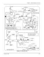
Page 37: ...REGULATOR OIL PRESSURE OIL MODULATING CAM PRESSURE GAUGE OIL BURNER CONTROLLER FUEL OIL VALVE OIL SOLENOID BACK PRESSURE ORIFICE OIL RETURN RECEIVER TANK AIR OIL LUBE OIL PROVING SWITCH ATOMIZING AIR LUBE OIL STRAINER SWING CHECK VALVE AIR STRAINER ATOMIZING AIR MANIFOLD BLOCK PRESSURE GAUGE NOZZLE AIR OIL BURNER NOZZLE INLET OIL FUEL AIR PUMP RETURN FUEL OIL VACUUM CHECK PRIMING VALVE OIL METERIN...

Page 38: ...ater when hot water is available The heated oil flows through a fuel oil strainer to prevent any foreign matter from entering the control valves and nozzle The fuel oil controller contains in a single unit the necessary valves regulators and gauges to regulate the pressure and flow of oil to the burner The program relay energizes or deenergizes the solenoid oil valve to permit or cut off oil flow ...

Page 39: ... OF DISCHARGE CORRESPONDING HOT WATER HEATING COMPONENTS STEAM GENERATORS REFER TO FIGURE 1 2 FOR NOTE DIAGRAM SHOWS COMPONENTS USED WITH BY PASS MANUAL VALVE FUEL OIL THERMOMETER REGULATOR OIL PRESSURE OIL MODULATING CAM PRESSURE RELIEF VALVE OIL RETURN PRESSURE GAUGE ORIFICED VALVE OIL BURNER PRESSURE GAUGE VALVE OIL METERING SWITCH TEMPERATURE LOW OIL CONTROLLER FUEL OIL VALVE OIL SOLENOID VALV...

Page 40: ...hes must be closed to prove sufficient but not excessive gas fuel pressure N MODULATING FIRING The modulating motor through a linkage arrangement controls the air damper and the butterfly gas valve or the oil metering valve to maintain a constant air fuel ratio throughout the firing range During burner operation the motor is controlled by a modulating pressure control on a steam boiler or by a mod...

Page 41: ...e motor The switch must be closed to establish that the damper and fuel metering valves are in the low fire position before the programmer commences into the ignition period During this time neither the manual flame control nor the modulating control have any control over the damper motor regardless of their setting An optionally equipped boiler uses a second integral switch to establish that the ...

Page 42: ...Chapter 2 Burner Operation and Control 2 22 Part No 750 184 ...

Page 43: ...3 Waterside Care and Requirements A GENERAL 3 2 B WATER REQUIREMENTS 3 2 C WATER TREATMENT 3 7 D CLEANING 3 8 E BOIL OUT OF A NEW UNIT 3 9 F WASHING OUT 3 12 G BLOWDOWN STEAM BOILER 3 12 H PERIODIC INSPECTION 3 15 I PREPARATION FOR EXTENDED LAY UP 3 16 ...

Page 44: ...erated as intended by its designer in order to avoid thermal shock or severe possibly damaging stresses from occurring to the pressure vessel Note This manual only covers boilers using water Glycol solutions have different operating requirements circulation rates and temperatures etc B WATER REQUIREMENTS 1 HOT WATER BOILER Air Removal The hot water outlet includes a dip tube which extends 2 to 3 i...

Page 45: ...nded that they be kept running even though the heat users do not require hot water The relief device or by pass valve will thus allow continuous circulation through the boiler and can help prevent rapid replacement of boiler water with cold zone water Continuous Flow Through the Boiler The system should be piped and the controls arranged to allow water circulation through the boiler under all oper...

Page 46: ...mp is running Pressure The design of the system and usage requirements often dictate the pressure exerted upon the boiler Some systems are pressurized with air or with an inert gas such as nitrogen Caution must be exercised to ensure that the proper relationship of pressure to temperature exists within the boiler so that all of the boiler s internal surfaces are fully wetted at all times For this ...

Page 47: ...8 67 59 52 47 80 2 680 536 268 179 134 107 90 77 67 60 54 100 3 350 670 335 223 168 134 112 96 84 75 67 125 4 185 836 418 279 209 168 140 120 105 93 84 150 5 025 1 005 503 335 251 201 168 144 126 112 100 200 6 695 1 340 670 447 335 268 224 192 168 149 134 250 8 370 1 675 838 558 419 335 280 240 210 186 167 300 10 045 2 010 1 005 670 503 402 335 287 251 223 201 350 11 720 2 350 1 175 784 587 470 39...

Page 48: ...n established close the boiler feed pump entrance switch The pump should shut down when the water level reaches the proper level Feedwater pumps must have adequate capacity to maintain required water level under all operating conditions Check the feedwater pumps periodically and maintain as necessary to prevent unexpected breakdowns Note Prior to operating the pump carefully check the alignment of...

Page 49: ...valves Warning The isolation valves and the water column piping must be locked open during operation Failure to do so may result in a low water condition Failure to follow these instructions could result in serious personal injury or death C WATER TREATMENT Properly treated boiler feed water coupled with good engineering and operating practices lead to maximum effectiveness and long trouble free l...

Page 50: ...oiler water and condensate The internal or waterside surfaces of the pressure vessel should be inspected with enough frequency to determine the presence of any contamination accumulations of foreign matter or corrosion and or pitting If any of the conditions are detected contact your local Cleaver Brooks authorized representative for advice on corrective action A properly sized water meter should ...

Page 51: ...el waterside should be inspected on a periodic basis An inspection will reveal true internal conditions and serve as a check against conditions indicated by chemical analysis of the boiler water Inspection should be made three months after initial starting and at regular 6 9 or 12 month intervals thereafter The frequency of further periodic inspections will depend upon the internal conditions foun...

Page 52: ...suggested general procedure for cleaning a boiler is as follows 1 Refer to Table 3 2 to determine water capacity Have sufficient cleaning material on hand to complete the job 2 When dissolving chemicals the following procedure is suggested Warm water should be put into a suitable container Slowly introduce the dry chemical into the water stirring it at all times until the chemical is completely di...

Page 53: ...ove handhole plates and wash the waterside surfaces thoroughly using a high pressure water stream 12 Inspect the surfaces If they are not clean repeat the boil out 13 After closing the handholes and reinstalling the safety or relief valves fill the boiler and fire it until the water is heated to at least 180 F to drive off any dissolved gases which might otherwise corrode the metal The above proce...

Page 54: ...uld be removed and waterside surfaces should be inspected for corrosion pitting or formation of deposits Flushing of Pressure Vessel Interior Upon completion of the inspection the pressure vessel interior should be flushed out as required with a high pressure hose If deposits are not fully removed by flushing a consultation may be required with your local Cleaver Brooks authorized representative I...

Page 55: ...ater is thickened with the solids If the concentration is permitted to accumulate foaming and priming will occur and the sludge can cause harmful deposits that bring about overheating of the metal The lowering or removal of the concentration requires the use of boiler water blowdown 1 TYPES OF BLOWDOWN There are two principal types of blowdown intermittent manual blowdown and continuous blowdown I...

Page 56: ...y blows The length and frequency of the blwdown is particularly important when the suspended solids content of the water is high With the use of frequent short blows a more uniform concentration of the pressure vessel water is maintained In cases where the feedwater is exceptionally pure or where there is a high percentage of return condensate blowdown may be employed less frequently since less sl...

Page 57: ...1 2 is often acceptable as a guide to adequate blow However lowering the water 1 2 should not be interpreted as a rule since water analysis procedures should prevail If the glass cannot be viewed by the party operating the valve another operator should watch the glass and direct the valve operator Close the downstream slow opening valve first and as fast as possible Then close the valve next to th...

Page 58: ... from the waterside surfaces and check for internal or external corrosion and leakage The fireside surface should also be thoroughly cleaned so that metal surfaces welds joints tube ends fittings and any previous repairs can be readily checked Be sure that steam valves and valves to expansion tank hot water feedwater valves blow off valves all fuel valves valves to expansion tank and electrical sw...

Page 59: ...es tube sheets and other fireside surfaces Brushing will generally suffice Sweep away or vacuum any accumulation The fireside surfaces may be flushed with water However all moisture must be eliminated after flushing and the surface dried by blowing air or applying some form of heat It is good practice to protect the cleaned surfaces by coating them with an anti corrosive material to prevent rust T...

Page 60: ...gested that the pressure vessel be drained thoroughly cleaned internally and re filled to overflowing with treated water If deaerated water is not available the unit should be fired to boil the water for a short period of time Additional chemicals may be suggested by your local Cleaver Brooks authorized representative to minimize corrosion Internal water pressure should be maintained at greater th...

Page 61: ...Milwaukee Wisconsin www cleaver brooks com Chapter 4 Sequence of Operation A GENERAL 4 2 B CIRCUIT AND INTERLOCK CONTROLS 4 2 C SEQUENCE OF OPERATION OIL OR GAS 4 4 D FLAME LOSS SEQUENCE 4 6 ...

Page 62: ...m boiler or the operating limit temperature control hot water boiler and high limit pressure or temperature control are below their cutoff setting All applicable limits are correct for burner operation The load demand light glows All entrance switches are closed and power is present at the line terminals of Blower motor starter Air compressor motor starter if provided Oil heater relay if provided ...

Page 63: ... and 6 oil only Low gas pressures switch LGPS High gas pressure switch HGPS LE Proximity switch interlock Fuel valve interlock circuit Main gas valve auxiliary switch MGVAS Oil valve auxiliary switch OVAS Blower Motor Starter Circuit Blower motor starter BMS Air compressor motor starter ACMS if provided Air purge valve APV Nos 5 or 6 oil only Running lnterlock Circuit Blower motor starter interloc...

Page 64: ...ng conditions satisfied Pre Purge Cycle When the burner switch BS is turned on and controls wired in the limit and fuel valve interlock circuits are closed and no flame signal is present the blower motor start circuit is powered energizing the blower motor starter BMS The load demand light LDL turns on When firing oil the air compressor motor starter ACMS if provided is also powered Air purge valv...

Page 65: ...tical The pilot flame must be established and proven by the flame detector FD within a 10 second period in order for the ignition cycle to continue If for any reason this does not happen the system will shut down and safety lockout will occur Notice Note Depending upon the requirements of the regulatory body insurer or fuel being burned either the 10 or 15 second pilot ignition terminal may be use...

Page 66: ...st on a No 6 oil burner The burner starting cycle is now complete The LDL and FVL lights on the panel remain lit Demand firing continues as required by load conditions Burner Shudown Post Purge The burner will fire until steam pressure or water temperature in excess of demand is generated With modulated firing the modulating damper motor MDM should return to the low fire position before the operat...

Page 67: ...ually reset before operation can be resumed refer to the previous caution 2 Pilot but no main flame When the pilot flame is proven the main fuel valve circuit is energized Depending upon the length of the trial for ignition period the pilot flame will be extinguished 10 or 15 seconds later The flame detecting circuit will respond to deenergize the main fuel valve circuit within 2 to 4 seconds to s...

Page 68: ...can be prevented by systematic checks of the actual operation against the normal sequence to determine the stage at which performance deviates from normal Following a routine may possibly eliminate overlooking an obvious condition often one that is relatively simple to correct Remember a safety device for the most part is doing its job when it shuts down or refuses to operate Never attempt to circ...

Page 69: ...or Fuses BMPR Blower Motor Power Relay BMPS Blower Motor Purge Switch BMR Blower Motor Relay BMS Blower Motor Starter BMSI Blower Motor Starter Interlock BMSS Boiler Master Selector Switch BS Burner Switch BSS Boiler Selector Switch BWPM Booster Water Pump Motor BWT Booster Water Thermostat C CAFL Combustion Air Failure Light CAFR Combustion Air Failure Relay CAP Capacitor CAPS Combustion Air Prov...

Page 70: ...l Valve HFPS High Furnace Pressure Switch HFS High Fire Switch HFS A High Fire Switch Air HGPL High Gas Pressure Light HGPR High Gas Pressure Relay MNEMONIC DESCRIPTION HGPS High Gas Pressure Switch HHFL Header High Fire Light H LWA High Low Water Alarm HLC High Limit Control HLFC High Low Fire Control HLPC High Limit Pressure Control HLTC High Limit Temperature Control HMC Header Modulating Contr...

Page 71: ...uit Breaker MPP Manual Positioning Potentiometer MR Manual Reset MTC Modulating Temperature Control MVA Make Up Valve Actuator N N Denotes Natural Gas Equipment Prefix MNEMONIC DESCRIPTION N C Normally Closed N O Normally Open NFL No Flow Light NFR No Flow Relay NGHPV Natural Gas Housing Purge Valve O ODA Outlet Damper Actuator ODM Outlet Damper Motor ODMAS Outlet Damper Motor Auxiliary Switch ODM...

Page 72: ...r SCTS Supervisory Cock Test Switch SDL Steam Demand Light SHT Steam Heater Thermostat SHV Steam Heater Valve SLCL Safety Limits Complete Light SPIR System Pump Interlock Relay SPS Steam Pressure Sensor SS Selector Switch SSC Sequencing Step Controller SSL Safety Shutdown Light SSR Solid State Relay SSV SpanSolenoid Relay STHWC Surge Tank High Water Control STHWL Surge Tank High Water Light STHWR ...

Page 73: ...NTROL SETTINGS STEAM AND HOT WATER 5 3 C GAS PILOT 5 4 D ATOMIZING AIR 5 4 E FIRING PREPARATIONS FOR NO 2 OIL SERIES 100 200 5 5 F FIRING PREPARATION FOR NO 6 OIL SERIES 400 600 5 7 G FIRING PREPARATIONS FOR GAS SERIES 200 400 700 5 9 H IFGR SETUP 5 10 I START UP OPERATING AND SHUTDOWN ALL FUELS 5 11 J CONTROL OPERATIONAL TEST AND CHECKS 5 16 ...

Page 74: ...r death Verify supply of fuel and proper voltage Check for blown fuses open circuit breakers dropped out overloads etc Check reset of all starters and controls having manual reset features Check the lockout switch on the programmer and reset if necessary The boiler should be filled with water to the proper operating level using water of ambient temperature Be sure that treated feedwater is availab...

Page 75: ...esired steam pressure but at least 10 lower than the setting of the safety valve 2 The operating limit temperature control on a hot water boiler should be set slightly above the highest desired water tempera ture and within the limits of the pressure vessel Inspect the High Limit Control for proper setting 1 On a high pressure steam boiler the high limit pressure control should be set approximatel...

Page 76: ...e correct If additional information is required see your local Cleaver Brooks authorized representative or contact Cleaver Brooks On initial start up or whenever the boiler is placed into operation from a cold start the Manual automatic Selector Switch should be set at manual and the Manual Flame Control set at close After the boiler is in operation and thoroughly warmed the selector switch should...

Page 77: ...gh fire Greater air pressure causes excessive wear of the air pump increases lube oil usage and can overload the motor thus causing damage to the equipment Note Abnormally high pressure indicated on the nozzle air pressure gauge is an indication that the burner nozzle has become clogged In the event of clogging check the nozzle and clean as necessary After air flow has been verified turn the burne...

Page 78: ...ht be caused by obstruction in the suction line excessive lift inadequate priming suction line leaks etc If oil flow is not readily established avoid prolonged operation of the pump to minimize risk of damage to internal parts of the pump If oil flow is not established after a second or third priming attempt a full investigation is required to determine the cause A vacuum or a compound pressure va...

Page 79: ...he burner drawer gun into its most forward position and latch it in place Oil Flow Open all valves in the oil suction and oil return lines Open the By pass Valve on the fuel oil controller until oil flow is established Normally the Orifice Valve is left in a closed position However on cold starts it may be opened for brief periods to aid in establishing oil flow The by pass and orifice valves must...

Page 80: ...follow these instructions could result in equipment damage Oil Temperature After determining that the heater shell is filled and that fuel oil circulation exists turn the oil heater switch to on Adjust the electric oil heater thermostat to maintain oil temperature at approximately 200 F The electric heater on burners equipped for No 6 fuel oil is sized so that it is capable of supplying heated oil...

Page 81: ...into the system to supervise purging of the new gas line unless they have already done so Determine that the pilot is operating properly as outlined in Section C Chapter 5 Determine that sufficient pressure exists at the entrance to the gas train by installing a test gauge downstream of the regulator The gas pressure regulator must be adjusted to the proper pressure level Since the regulator is ge...

Page 82: ...diately turn the Burner Switch off and close the main gas cock Investigate and correct the cause of the valve leakage before relighting the burner The main gas valve should provide a tight seal provided nothing prevents tight closure Foreign material may be present in either the new or renovated gas lines unless adequate care is taken in cleaning and purging When the conditions covered in Section ...

Page 83: ... Refer to Chapter 8 for instructions on cassette removal and installation I START UP OPERATING AND SHUTDOWN ALL FUELS Depending upon the fuel being burned the applicable previous sections in Chapter 5 should be reviewed for preliminary instructions When firing with oil be certain that the Burner Gun is in its most forward position and latched in place When firing with gas the burner gun should be ...

Page 84: ...F FUELS USED AND THE NOX LEVELS DESIRED ALL SINGLE FUELED BOILERS HAVE A SINGLE DRIVE ARM DUAL FUELED BOILERS MAY OR MAY NOT HAVE A DUAL ARM DEPENDING ON THE OPTION PURCHASED JACKSHAFT LINKAGE ROD POSITION LABEL BOILER HP 125 150 200 PPM NOX A B C D E F G H J K 60 30 25 20 20 25 30 60 20 25 30 60 8 8 40 40 20 20 20 20 40 40 8 8 20 20 40 40 8 8 10 10 10 10 10 10 3 8 13 16 13 16 3 8 13 16 3 8 2 2 3 ...

Page 85: ...ITION 90 SLOW OPENING DAMPER EXTERNAL ARM NOTE RECORD INSTALLED VALUES ON THIS ILLUSTRATION FOR FUTURE REFERENCE A ______ EXTERNAL ARM HOLE POSITION B ______ DEGREES AT THE TIME OF START UP VERIFIED AND RECORDED A D FLANGE COLLAR HOLE 1 HOLE 2 LINKAGE CONNECTION POINT B C NOTE RECORD INSTALLED VALUES ON THIS ILLUSTRATION FOR FUTURE REFERENCE A ______ FLANGE COLLAR SETTING B ______ DAMPER POSITION ...

Page 86: ...THE TEST VALVE when steam begins to appear A hot water boiler must have a continuous flow of system water through the vessel during the warm up period The entire water content of the system and boiler must be warmed prior to increasing fuel input If the flame at low fire provides insufficient heat to reach normal operating pressure or temperature after 30 minutes gradually increase the firing rate...

Page 87: ...urner off the load demand light no longer glows Shutdown through conditions causing safety or interlock controls to open will actuate the Flame Failure Light and alarm if so equipped and the Load Demand Light will remain lit The cause of this type of shutdown will have to be located investigated and corrected before operation can be resumed Refer to the trouble shooting section in Chapter 7 Shutdo...

Page 88: ...re range See Chapter 6 for instructions on the adjustment of controls The water temperature on a hot water boiler that may be operating at less than full load may be raised by manually increasing the firing rate until the burner shuts down through the action of the operating limit control Observe the thermometer to verify the desired settings at the point of cut out and again when the burner resta...

Page 89: ... Water 6 9 M COMBUSTION AIR PROVING SWITCH CAPS 6 10 N ATOMIZING AIR PROVING SWITCH 6 10 O GAS PILOT FLAME ADJUSTMENT 6 11 P GAS PRESSURE AND FLOW INFORMATION 6 13 Q GAS FUEL COMBUSTION ADJUSTMENT 6 16 R LOW GAS PRESSURE SWITCH 6 20 S HIGH GAS PRESSURE SWITCH 6 21 T FUEL OIL PRESSURE AND TEMPERATURE GENERAL 6 21 U FUEL OIL COMBUSTION ADJUSTMENT 6 22 V BURNER DRAWER ADJUSTMENT 6 24 W OIL DRAWER SWI...

Page 90: ...ed or that adjustments have not changed during shipment and installation The adjustment procedures in Chapter 6 apply to standard components furnished on steam or hot water boilers fired with gas and or the various grades of oil B LINKAGE MODULATING MOTOR AND AIR DAMPER The linkage consists of various arms connecting rods and swivel ball joints that transmit motion from the modulating motor to the...

Page 91: ...modulating motor in the low fire position the arm on its shaft should be at an angle of 45 below the horizontal The driven arm on the jack shaft should also be 45 below horizontal Secure both arms and fit the connecting linkage rod in place between them Refer to Figure 6 1 Position the oil and or gas modulating cams on the jackshaft so that the cam follower assembly is between the first and second...

Page 92: ...tor must be allowed to complete its full stroke and the damper must move freely from low to high fire position Adjustment of linkage connected to a gas butterfly valve is described in Section Q of Chapter 6 C MODULATING MOTOR The modulating motor has a 90 shaft rotation The motor manufacturer also provides a 160 stroke model for other applications If a replacement is obtained from someone other th...

Page 93: ...hen the demand is satisfied The control must be set to initiate startup only at the low fire position The Modulating Control senses changes in the hot water temperature or steam pressure and signals the modulating motor to control the flow of fuel and air to the burner With either steam or hot water boilers the modulating control must be set to ensure the burner is at its minimum low fire position...

Page 94: ...e Operating Limit Control will open As the pressure or temperature drops back to B the Operating Limit Control closes and the burner will restart The Modulating Control will signal the modulating motor to be in a low fire position If the load demands exceed the low fire input potential the Modulating Control will increase the firing rate proportionately as pressure or temperature falls toward poin...

Page 95: ...nder manual flame control until normal operating pressure or temperature is reached If the burner is not under manual control on a cold start it will immediately move toward high fire as soon as the program control releases the circuit that holds the burner in low fire The modulating control will be calling for high fire and the burner will move to that position as rapidly as the damper motor can ...

Page 96: ... the safety valve settings and should not exceed 90 of the valve setting The control requires manual resetting after it shuts off the burner In the setting of the controls consideration must be given to the time required for a burner restart Each start requires a prepurge period plus the fixed time required for proving the pilot and main flame In addition approximately one half minute is required ...

Page 97: ...urn the adjustment wheel until pointer indicates desired range Caution To prevent burner shutdown at other than low fire setting adjust modulating temperature control to modulate low fire BEFORE operating limit temperature control shuts off burner Failure to follow these instructions could result in damage to the equipment J OPERATING LIMIT TEMPERATURE CONTROL HOT WATER Set cut out burner off temp...

Page 98: ... switch could be set at gas to eliminate the atomizing air proving switch from the circuitry To have the modulating damper motor drive to high fire damper open remove the cover from the motor and remove the wire from terminal W Slowly turn down the Combustion Air Proving Switch adjusting screw until it breaks the circuit Here the programmer will lock out and must be manually reset before it can be...

Page 99: ...ly adjust the size of the pilot flame it is preferable to obtain a microamp or voltage reading of the flame signal The correct voltage or microamp readings can be found in the information supplied with the flame safeguard system The program relay used may be of the type that provides message information that includes a constant flame signal of dc voltage In this case a separate dc voltmeter is not...

Page 100: ...ust be accomplished within the time limit of the safety switch or approximately 30 seconds after the detector is removed If the control shuts down manually reset it Replace the detector and repeat the process from step 5 7 When a suitable flame as indicated in paragraph 6 is obtained replace the detector Observe the reading on the micro ammeter The reading should be between 2 1 4 and 5 microamps w...

Page 101: ...igh enough to overcome the pressure loss due to the frictional resistance imposed by the burner system and the control valves The pressure required at the entrance to the burner gas train for rated boiler output is termed net regulated pressure The gas pressure regulator must be adjusted to achieve the pressure to assure full input The pressure requirement varies with boiler size altitude and type...

Page 102: ...le 6 2 Gas pressure requirements NTI gas trains CB LE 125 200 HP CBLE 15 PPM CBLE 9 PPM Boiler HP Gas Train Size in Pressure Range PSI Gas Train Size in Pressure Range PSI 125 1 5 3 3 6 0 1 5 3 3 6 0 150 1 5 3 9 6 0 1 5 4 1 6 0 200 1 5 4 5 7 0 1 5 4 5 7 0 Table 6 3 Gas pressure requirements standard and oversize gas trains CB Ohio Special 100 225 HP Boiler HP Gas Train Size In Min Pressure Max Pre...

Page 103: ... meter to deliver the equivalent number of cubic feet at base pressure As an example Assume that a 200 horsepower boiler is installed at 2 000 feet above sea level is equipped with a standard gas train and a high turndown burner and that 1 000 Btu natural gas is available with an incoming gas pressure of 3 psig The pressure and flow requirements can be determined as follows Table 6 4 Pressure Corr...

Page 104: ...00 8 369 CFH At 14 7 Ib atmospheric base 1 000 pressure THEN 8 369 7 092 CFH 1 18 This is the CFH at line pressure that must pass through the meter so that the equivalent full input requirement of 25 100 CFH at base pressure will be delivered Checking Gas Flow Your gas supplier can generally furnish a gas meter flow chart from which gas flow can be determined After a short observation period the i...

Page 105: ...ere must always be excess air in the combustion process to account for changes in boiler room temperature and atmospheric conditions and to ensure the combustion is on the proper side of the combustion curve Proper setting of the air fuel ratios at all rates of firing must be established by the use of a combustion or flue gas analyzer The appearance or color of the gas flame is not an indication o...

Page 106: ...ucts of combustion for a typical flue gas analysis natural gas One of the products of combustion is CO2 Carbon Dioxide This is shown in percentage Another product of combustion is CO carbon monoxide and is shown in both percentage and parts per million ppm The maximum CO level standardly allowed is less than 400 ppm However this may change subject to local regulations The percent O2 recorded on an...

Page 107: ...oring combustion for overly rich or lean conditions Set and lock the high fire stop screw so that it is just touching the valve arm Determine the actual gas flow from a meter reading See section P of Chapter 6 With the butterfly valve open and with regulated gas pressure set at the calculated pressure the actual flow rate should be close to the required input If corrections are necessary increase ...

Page 108: ...e to loosening and a lubricant could damage equipment Standard Burner Low Fire Adjustment The fuel input should be adjusted using the low fire cam screw to approximately 25 of that at high fire Table 6 6 At low fire the O2 flue gas reading should be between 6 7 It may be necessary to readjust the setting of the low fire stop screw to obtain the proper air fuel ratio at the low fire rate To ensure ...

Page 109: ...L Variations in burning characteristics of the fuel oil may occasionally require adjustments to assure highest combustion efficiency The handling and burning characteristics may vary from one delivery of oil to another Therefore it is recommended that the oil system be inspected from time to time to verify that pressures and viscosity are at the proper operating levels Because of variation in oils...

Page 110: ...s firing the pump must operate for a sufficient period of time to cool the oil heater Similarly if an electric steam or hot water oil heater is removed for servicing the temperature of the heater should be reduced by circulating oil until it has cooled U FUEL OIL COMBUSTION ADJUSTMENT After operating for a sufficient period of time to assure a warm boiler adjustments should be made to obtain effic...

Page 111: ...re should be tested The burner manufactures recommendations on turndown should also be followed and the turndown range of the burner should not be exceeded It is required to set the burner to operate with a reasonable amount of excess air to compensate for minor variations in the pressure temperature or burning properties of oil Fifteen to 20 excess air is considered reasonable This would result i...

Page 112: ... stopping at each adjusting screw until the low fire position is reached Note Do not use any lubricant on the adjusting setscrews These have a nylon locking insert intended to provide locking torque and resistance to loosening and a lubricant could damage the equipment Standard Burner Low Fire Adjustment Heavy Oil The fuel input should be adjusted with the low fire cam screw to approximately 25 of...

Page 113: ... OIL DRAWER SWITCH The integral contacts of the control are closed by proper positioning and latching of the oil drawer in its forward position Figure 6 17 Adjustment of the switch must be such that its contacts open if the oil drawer is not properly positioned for oil firing The switch is BURNER BACKPLATE ASSEMBLY NOZZLE AIR PRESSURE GAUGE NEOPRENE O RING OIL INLET ATOMIZING AIR INLET IGNITION EL...

Page 114: ...F above the normal operating temperature The controls generally have a set differential and will close 5 F below the setpoint Z LOW OIL PRESSURE SWITCH The L O P S prevents burner ignition or stops its operation when the oil pressure is below the set point Adjust the control by turning the screw on top of control case to an indicated pressure 10 psi below the established primary oil pressure setti...

Page 115: ...th a hot water oil heater has a built in adjustable thermostat The maximum temperature setting is stamped on its dial The desired temperature can be obtained by turning the adjusting screw The thermostat should be set at a temperature approximately 15 degrees lower than the hot water heater thermostat Such a temperature prevents the electric heater from operation when the water heater is functioni...

Page 116: ...Chapter 6 Adjustment Procedures 6 28 Part No 750 184 ...

Page 117: ...he programmer and other controls in the system may be obtained by studying the contents of this manual Knowledge of the system and its controls will make trouble shooting much easier Costly down time or delays can be prevented by systematic checks of actual operation against the normal sequence to determine the stage at which performance deviates from normal Following a routine may possibly elimin...

Page 118: ... low pressure and high pressure switches D Oil fired unit burner gun must be in full forward position to close oil drawer switch E Heavy oil fired unit oil temperature below minimum settings 4 Fuel valve interlock circuit not completed A Fuel valve auxiliary switch not enclosed NO IGNITION 1 Lack of spark A Electrode grounded or porcelain cracked B Improper electrode setting C Loose terminal on ig...

Page 119: ... fuel D Main oil valve inoperative E Check oil nozzle gun and lines 4 Flame detector defective sight tube obstructed or lens dirty 5 Insufficient or no voltage at main fuel valve circuit terminal BURNER STAYS IN LOW FIRE 1 Pressure or temperature above modulating control setting 2 Manual automatic switch in wrong position 3 Inoperative modulating motor see Section F 4 Defective modulating control ...

Page 120: ...ng fuel supply 1 Temporary obstruction in fuel line 2 Temporary drop in gas pressure 3 Orifice gate valve accidentally opened heavy oil 8 Interlock device inoperative or defective MODULATING MOTOR DOES NOT OPERATE 1 Manual automatic switch in wrong position 2 Linkage loose or jammed 3 Motor does not drive to open or close during pre purge or close on burner shutdown A Motor defective B Loose elect...

Page 121: ... SOLENOID VALVES 8 11 K AIR CONTROL DAMPER LINKAGE CAM SPRING 8 11 L FORCED DRAFT FAN 8 12 M CB LE FAN MOTOR CASSETTE REMOVAL 8 13 N CB LE INSPECTION AND ADJUSTMENT 8 13 O CB LE AIRBOX GASKET INSTALLATION 8 14 P CB LE FAN MOTOR CASSETTE INSTALLATION 8 15 Q SAFETY VALVES 8 15 R FUEL OIL METERING VALVE 8 16 S AIR PUMP AND LUBRICATING SYSTEM 8 17 T HEAD INSPECTION AND MAINTENANCE 8 21 U REFRACTORY 8 ...

Page 122: ...l devices that make it automatic or semi automatic in operation the devices require systematic and periodic maintenance Any automatic feature does not relieve the operator from responsibility but rather frees the operator from certain repetitive chores providing time to devote to upkeep and maintenance Alertness in recognizing an unusual noise improper gauge reading leaks etc can make the operator...

Page 123: ...entative B FIRESIDE CLEANING Soot and non combustibles are effective insulators and if allowed to accumulate will reduce heat transfer to the water and increase fuel consumption Soot and other deposits can be very moisture absorbent and may attract moisture to form corrosive acids that will deteriorate fireside metal Clean out should be performed at regular and frequent intervals depending upon lo...

Page 124: ...etion of the procedure the Level Master will indicate a successful blowdown and will time stamp the event and record it in controller memory The Level Master also has provisions to test the Auxiliary Low Water Cutoff ALWCO To perform the test open the bottom blowdown valves with the boiler running When the water level reaches the ALWCO setpoint the Level Master will shut down the boiler Restore wa...

Page 125: ... low pressure air Take care not to damage the mechanism Examine any mercury tube switches for damage or cracks Dark scum over the normally bright surface of the mercury may lead to erratic switching action Be certain that controls are correctly leveled The piping leading to the pressure control actuators should be cleaned if necessary Covers should be left on controls at all times Dust and dirt ca...

Page 126: ...Chapter 8 Inspection and Maintenance 8 6 Part No 750 184 ...

Page 127: ...ions demand Use a soft cloth moistened with detergent to clean the lens A safety check procedure should be established to test the complete safeguard system at least once a month or more often Tests should verify safety shutdown and a safety lockout upon failure to ignite the pilot upon failure to ignite the main flame and upon loss of flame Each of the conditions should be checked on a scheduled ...

Page 128: ...ion to the diffuser and other components is important for proper firing and should be checked Oil Strainers Oil strainers should be cleaned frequently to maintain a free and full flow of fuel Light Oil Strainers The fuel oil strainer screen must be removed and cleaned at regular intervals It is advisable to remove the screen each month and clean thoroughly by immersing it in solvent and blowing it...

Page 129: ...and swirler are a matched set which are precision lapped at the time of assembly The close fit of the lapped surfaces must be maintained in order to provide optimum performance Additional lapping may be required to provide better atomization for more efficient combustion Do not interchange parts if a spare is kept In reassembling be certain that the seating spring is in place and that it is holdin...

Page 130: ...hould be 1 4 between the edge of the diffuser fins and the gas spuds when the burner is installed Check to see that the diffuser fins do not interfere with the gas ports or gas spuds in the burner housing See Section V in Chapter 6 for more information Check the electrode setting for any cracks that might be present on the porcelain insulator Replace the electrode if cracking is evident since crac...

Page 131: ...ckshaft damper control rod disconnected the air control damper should rotate freely through its entire range of movement Any resistance to movement or excessive play in the support bearing should be investigated and corrected before the burner is put back in operation The overall tightness of the linkage assembly should be checked monthly If necessary tighten the setscrews and the connections at t...

Page 132: ... constant and within the specified 0 030 0 050 clearance 8 Install the air duct assembly through the head opening Tighten the screws securing the air duct to the fan housing only enough to create a seal between the neoprene gasket and the housing 9 After connecting the motor leads verify that the impeller rotation is counter clockwise when viewed from the motor end Notice Note If the boiler is ins...

Page 133: ...g the fan motor cassette removal Failure to follow these instructions can result in damage to the equip ment 3 Swing the fan motor cassette to the side and secure it to the boiler using high strength cord Do not over extend the motor wires N CB LE INSPECTION AND ADJUSTMENT NOx levels should be checked periodically to ensure compliance with all local and federal regulations as well as to ensure tha...

Page 134: ... Adjust the retainers for the correct impeller clearance at two housing attachment points 180 apart C Adjust the retainers for correct clearance at the housing attachment points 90 from those initially adjusted D Adjust for correct impeller clearance at the remaining attachment points 5 Check and replace any gaskets that have been damaged Gaskets that have been in use for one year or more should b...

Page 135: ... secured to the front head reconnect the davit to the front door by screwing in the retaining bolt at the top centerline Check occasionally that the fan is securely tightened to the motor shaft Check the clearance between the fan vanes and housing as outlined above Notice Note If the boiler is installed in a dusty location check the vanes occasionally for deposits of dust or dirt These buildups ca...

Page 136: ... off the packing gland 6 Remove the capscrews holding the jack shaft support bracket so that the bracket can be moved It may also be necessary to loosen the supporting bracket on the far end of the shaft 7 Remove the existing packing and guides Do not reuse the packing and guides 8 Lightly coat the stem with the lubricant provided with the packing kit Place the new packing O rings and guides onto ...

Page 137: ...hich may have entered the valves Clean out carefully and reassemble It is recommended that the diaphragms be replaced annually S AIR PUMP AND LUBRICATING SYSTEM Air Pump The air pump itself requires little maintenance However the life of the pump is dependent upon a sufficient supply of clean cool lubricating oil The oil level in the air oil tank must be observed closely Lack of oil will damage th...

Page 138: ...rom the compressed air The pads play a very important role and should be replaced semi annually It is also important that a proper grade of steel wool be used Only No 3 coarse grade American steel wool or equal CB919 124 should be used Three pads are required When replacing the wool insert two pads into the cylinder Alternate the grain of the pads Install the spacer with its stub end toward the op...

Page 139: ...gap by loosening the hold down bolts and shifting either the pump or the motor as required Generally a slight tapping on either the front or rear legs is all that is needed to obtain lateral adjustment Rear legs may require shimming for vertical correction Tighten the hold down bolts after adjustments are made and recheck alignment Calipers can also be used to check angular alignment Measure the o...

Page 140: ...ere should be approximately 7 8 space between the two shafts Place the coupling insert between the coupling halves prior to reassembly Check that both shafts rotate freely Refer to the previous section on coupling alignment instructions If shims were used originally under either pump brackets or motor feet be sure that they are correctly reinstalled When reinstalling the fan slide the hub on the p...

Page 141: ...he fuel lines Disconnect the main gas line coupling the pilot line and the sight port air line If the boiler is oil fired remove the supply and return oil lines and the oil pilot line if necessary Remove the head bolts and swing the head The opened head should be supported by blocking or jacking to eliminate possible deformation of the head or hinge area Front Head Inspect the second to third pass...

Page 142: ...e outer surface of the door does not necessarily indicate refractory trouble but may be an indication of other conditions such as 1 Leaking gaskets 2 Improper seal 3 Door retaining bolts insufficiently or unevenly tightened 4 The air line to the rear sight tube may be blocked or loose 5 Door was repainted with other than heat resistant paint Therefore before assuming that the refractory requires r...

Page 143: ... some time and exposure to ambient temperature or rapid cooling may cause refractory cracking and or harm to the boiler and door metal Warning Be certain that the davit arm is under tension before opening Failure to follow these instructions can result in serious personal injury or death Before loosening the door bolts tighten the nut on the davit stud to ensure tension on the davit arm Putting th...

Page 144: ... seal area of the tube sheet Apply blanket insulation 872 1073 to this area Refer to Figure 8 3 CB OS Attach new tadpole gasket with fasteners 841 00507 Apply spray adhesive 797 1813 around the inner circumference of the gasket Apply blanket insulation 872 1073 to this area Refer to Figure 8 3 Apply spray adhesive to the refractory to tubesheet seal area see detail Figure 8 3 Apply blanket insulat...

Page 145: ...d by the operator when the boiler is opened for inspection Furnace Liner Maintenance consists of occasional wash coating of the entire liner Face all joints or cracks by applying high temperature bonding mortar with a trowel or fingertips Wash coating should be done as soon as cracks are detected Should segments of the liner burn away or fall out replace the entire refractory Any refractory that m...

Page 146: ... of refractory cement Thin joints less than 1 16 are desirable Generally it will be necessary to shave a portion from one or more tiles to obtain a fit If a fill piece is required cut it to fit and install the piece at the bottom of the furnace Allow refractory to air dry as long as possible If immediate use is required fire intermittently at a low rate for several hours to thoroughly dry the refr...

Page 147: ...for 10 to 20 minutes to expel any excess grease The filler and drain plugs should be thoroughly cleaned before they are replaced The lubricant used should be clean and equal to one of the good commercial grades of grease locally available Control Linkage Apply a non gumming dripless high temperature lubricant such as graphite or a silicone derivative to all pivot points and moving parts Work lubri...

Page 148: ...rect replacement of wires Finish the cleaning process with a cleaning solvent to cut all hardened deposits from the heater element Because of the insulating effect of carbon and sludge periodic cleaning is necessary to prevent overheating of the elements If operation of the heater becomes sluggish examine the elements at once and clean as required Inspect the shell or tank each time the heater is ...

Page 149: ...ariations in fuel composition A combustion analyzer should be used to adjust air fuel ratio for maximum operating efficiency If your burner requires adjustments contact your local Cleaver Brooks authorized representative for assistance CB LE IFGR Maintenance Daily Check visually for free movement of IFGR linkage Quarterly Manually check for free movement of IFGR linkage Inspect and clean IFGR damp...

Page 150: ...h with use and proper tension should be maintained Do not apply excessive tension The air pump can be moved the small distance necessary for belt adjustment without any change of piping On a combination fired unit it is an acceptable practice to remove the belt when gas is being used for extended periods It is not absolutely necessary to do this however pump and belt life will be extended if the b...

Page 151: ...description and the quantity of parts desired together with the complete nameplate data including all electrical requirements WHERE TO ORDER PARTS Repair and replacement parts should be ordered from your local Cleaver Brooks authorized representative Contact your local Cleaver Brooks authorized representative for prompt supply of replacement parts ...

Page 152: ... Entrance Box 9 22 Front Head Electrical CB LE 9 23 Front Head Electrical CB OS 9 25 Straight Electric Oil Heater 60 Heavy Oil 9 27 Heavy Oil Piping 60 Steam 9 29 Common Oil Parts Heavy Oil 9 31 Side Mounted Air Compressor Piping 9 32 Air Compressor Piping CB OS 9 33 Air Line Piping 9 34 Light Oil Piping 9 35 Light Oil Air Piping Front Head 9 36 Pilot Gas Train 125 150HP CB LE 125 175HP CB OS 9 38...

Page 153: ...Chapter 9 Parts Part No 750 184 9 3 Insulated Front Head Model CB LE ...

Page 154: ...Chapter 9 Parts 9 4 Part No 750 184 Insulated Front Head Interior Model CB LE ...

Page 155: ...Chapter 9 Parts Part No 750 184 9 5 Insulated Inner Door Model CB OS ...

Page 156: ...Chapter 9 Parts 9 6 Part No 750 184 Insulated Rear Head CB LE ...

Page 157: ...Chapter 9 Parts Part No 750 184 9 7 Insulated Rear Head CB LE ...

Page 158: ...Chapter 9 Parts 9 8 Part No 750 184 Insulated Rear Head CB OS ...

Page 159: ...Chapter 9 Parts Part No 750 184 9 9 Dry Oven Model CB LE ...

Page 160: ... 894 3516 894 3525 15 894 3561 894 3561 600V MOTOR 5 5 H P 200 230 894 3564 894 3564 460V 60 HZ ODP 894 3567 894 3567 200 230 460V TEFC HI EFF MOTOR H P 5 5 50 HZ NOTE Impeller size is based on boiler hp ppm emission level boiler operating pressure and alti tude To ensure proper sizing for your application contact CB Aftermarket Impeller selection Ohio boilers Boiler HP 60 Hz 50 Hz 125S 192 C 42 1...

Page 161: ...Chapter 9 Parts Part No 750 184 9 11 Motor Impeller Model CB LE ...

Page 162: ...Chapter 9 Parts 9 12 Part No 750 184 Front Head Linkage ...

Page 163: ...Chapter 9 Parts Part No 750 184 9 13 Jackshaft Retrofit Assembly Kits 1 6 6 1 2 5 2 4 2 4 3 CB PART 274 221 1 6 6 1 2 4 5 2 3 CB PART 274 220 1 6 6 1 2 4 3 CB PART 274 63 ...

Page 164: ...EQ Part Description 1 1 67 16 Activation Rod 2 2 883 17 Ball Joint 3 2 10 288 Ball Joint Bushing 4 1 2 47 Modulation Motor Arm 5 2 869 21 Hex Nut 1 4 20 6 2 869 22 Hex Nut 3 8 24 7 2 860 39 Set Screw 8 1 868 138 Capscrew 1 4 20 1 1 4 LG 9 2 868 139 Capscrew 1 4 20 1 1 2 LG 10 Not Used 11 1 2 96 Damper Motor Arm ...

Page 165: ...kage Kit 2 3 4 7 5 4 3 2 5 1 7 CB PART 476 54 Item REQ Part Description 1 1 67 109 Damper Linkage Rod 2 2 883 17 Ball Joint 3 2 10 288 Ball Joint Bushing 4 2 869 21 Hex Nut 1 4 20 5 2 869 22 Hex Nut 3 8 24 6 Not Used 7 2 860 39 Capscrew 1 4 20 1 1 2 LG ...

Page 166: ... Pilot Models 100 600 125 200HP CB LE 23 41 35 42 33 18 31 46 19 17 36 24 15 22 1 28 30 40 5 3 4 D IR E C T IO N T O O P E N 1 29 43 13 12 8 26 28 27 23 7 6 20 21 23 14 39 2 16 23 9 1 4 11 22 23 9 25 10 44 45 7 16 1 4 MAX 3 32 MIN 1 MIN 1 8 3 16 16 1 4 17 ...

Page 167: ...14 1 59 5768 15 1 827 6 16 1 22 A 122 17 2 860 91 18 3 952 92 19 2 869 9 20 1 56 A 21 21 1 869 36 22 5 860 158 23 9 860 39 HOLDER ELECTRODE O RING SET SCREW SOCKET HD 5 16 18 NC X 1 2 MACHINE SCREW 10 24 NC RD H X 1 8 CAPSCREW SOCKET HD 1 4 20 X 1 2 LG SEALER RING NOT USED NOT USED CONNECTOR BOX SQUEEZE TYPE ARM DAMPER NOT USED MACH SCREW RD HD 1 4 20 X 1 2 LG CONNECTOR BOX SQUEEZE TYPE BRACKET LI...

Page 168: ... 22 13 7 28 26 27 25 3 NPT PLUG SEE DETAIL A 14 12 15 BAFFLE ATTACHMENT STUD BAFFLE SEAL BAFFLE FRONT EXTENSION TUBE SHEET INNER DOOR 876 A 73 AFTER CUTTING THREADS PER INSTRUCTIONS ON DRAWING 2 PAINT WITH SYNCRON 5112 ZINCOAT SHELL WITH ITEM 12 1 SEAL BAFFLE AT TUBE SHEET AND NOTES 16 18 17 1 2 DETAIL A 4 USED ON CB 125 150 USED ON CB 200 4 13 13 3 DIFFUSER TO BE FLARED TO MATCH I D OF BURNER OPE...

Page 169: ...TABLE 1 4 32 A 603 1 5 NAT GAS COMBINATION OR PROPANE 900 79 1 6 CB125 200 465 B 1330 1 7 1 868 157 6 8 NAT GAS COMBINATION OR PROPANE 853 348 1 NAT GAS COMBINATION OR PROPANE 65 A 704 1 10 11 3 860 15 NAT GAS COMBINATION OR PROPANE 12 6 OZ 872 558 13 1 40 D 540 14 4 869 29 15 8 952 325 16 24 841 A 551 17 8 FT 971 291 18 1 853 394 19 1 869 30 OIL ONLY 20 1 952 93 OIL ONLY 21 1 868 157 OIL ONLY 22 ...

Page 170: ...Chapter 9 Parts 9 20 Part No 750 184 Control Cabinet Hawk ICS ...

Page 171: ...Chapter 9 Parts Part No 750 184 9 21 Control Panel Standard ...

Page 172: ...Chapter 9 Parts 9 22 Part No 750 184 Entrance Box ...

Page 173: ...Chapter 9 Parts Part No 750 184 9 23 Front Head Electrical CB LE ...

Page 174: ...Chapter 9 Parts 9 24 Part No 750 184 Front Head Electrical CB LE ...

Page 175: ...Chapter 9 Parts Part No 750 184 9 25 Front Head Electrical CB OS ...

Page 176: ...Chapter 9 Parts 9 26 Part No 750 184 Front Head Electrical CB OS ...

Page 177: ...6 1 MIN B B 32 20 15 OIL INLET 7 9 9 A A 31 8 1 2 6 1 4 VIEW A A 31 REF 17 3 16 30 VIEW B B 32 15 21 1 ALL DIMENSIONS ARE APPROX NOTES 2 UNLESS OTHERWISE NOTED ALL PIPE TO BE 3 4 SCH 40 ASTM A120 WELDED BLACK STL AND ALL FITTINGS 150 M I 3 USE ITEM 27 WITH 836 72 HOTS 4 USE ITEM 27 WITH 836 65 LOTS 5 SUPPLY TEES ONLY IF REQUIRED BY INSURANCE 6 FOR HAWK DO NOT USE ITEM 10 USE QTY 2 OF ITEM 3 7 ITEM...

Page 178: ...952 93 853 227 952 92 868 138 868 405 8 A 65 BRACKET PIPE CAPSCREW HEX HD 1 4 20 x 7 8 CAPSCREW HEX HD 1 4 20 x 1 1 4 LOCKWASHER 1 4 GASKET HEATER LOCKWASHER 3 8 RELIEF VALVE 1 2 N P T PRESSURE GAUGE 845 313 ELBOW FLARED 90 SWIVEL JOINT 90 847 1715 1 1 1 1 2 2 1 STRAP PIPE 3 4 928 45 7 4 2 BUSHING 1 1 4 x 3 4 847 431 2 8 A 656 HEATER BRACKET 2 2 4 8 8 1 2 1 1 1 1 USED ON U BOLT 2 ELEMENT HEATER 1 ...

Page 179: ...Chapter 9 Parts Part No 750 184 9 29 Heavy Oil Piping 60 Steam CB LE ...

Page 180: ...Chapter 9 Parts 9 30 Part No 750 184 Heavy Oil Piping 60 Steam CB LE SEE TABLE NEXT PAGE ...

Page 181: ...Chapter 9 Parts Part No 750 184 9 31 Common Oil Parts Heavy Oil ...

Page 182: ...Chapter 9 Parts 9 32 Part No 750 184 Side Mounted Air Compressor Piping ...

Page 183: ...Chapter 9 Parts Part No 750 184 9 33 Air Compressor Piping CB OS ...

Page 184: ... 1 3 BULK CONDUIT 1 2 THINWALL EMT X A LG APPROX 1 2 BULK CONDUIT 1 2 THINWALL EMT X B LG APPROX 1 1 DESCRIPTION PART NO QTY ITEM 827 8 868 136 5 CAPSREW HEX HD 1 4 20 X 3 4 LG 7 COUPLING 1 2 CONDUIT CONNECTOR STRAIGHT 1 2 EMT CONDUIT 8 848 325 848 141 2 1 1 1 848 398 9 COUPLING UNION 1 2 EMT CONDUIT ELBOW STREET 1 2 X 45 SEE NOTE 3 6 859 118 1 VIEW A A 3 5 4 A A ...

Page 185: ...Chapter 9 Parts Part No 750 184 9 35 Light Oil Piping ...

Page 186: ...Chapter 9 Parts 9 36 Part No 750 184 Light Oil Air Piping Front Head ...

Page 187: ...Chapter 9 Parts Part No 750 184 9 37 Light Oil Air Piping Front Head PAGE 9 31 ...

Page 188: ...N DV 6HUYLFH 7HH HDG 137 URQ H 5HJXODWRU DV 3UHVVXUH 137 8 35 6685 137 RWWRP 0RXQW 9DOYH 6ROHQRLG 137 1 36 7 5 8 1 137 0 2 137 0 1 33 3 3 60 6 136 6 1 33 3 3 60 6 136 6 8 3 3 60 6 136 6 1 33 3 3 60 6 136 6 81 21 137 0 1 33 6 6 5 211 725 0 6 5 2 7 137 ODPS 3LSH RU 5LJLG RQGXLW 2QH ROH 6 5 7 2 6 5 187 81 36 5 81 7XELQJ VVHPEO DV 3LORW ...

Page 189: ...37 URQ H 5HJXODWRU DV 3UHVVXUH 137 8 35 6685 137 RWWRP 0RXQW 9DOYH 6ROHQRLG 137 1 36 7 5 8 1 137 0 2 137 0 1 33 3 3 60 6 136 6 9DOYH 5HOLHI 137 6SULQJ 5DQJH 1 33 3 3 60 6 136 6 1 33 3 3 60 6 136 6 81 21 137 0 8 3 3 60 6 136 6 1 33 6 6 5 7XELQJ VVHPEO DV 3LORW 211 725 0 6 5 2 7 137 ODPS 3LSH RU 5LJLG RQGXLW 2QH ROH 36 5 81 6 5 7 2 6 5 187 81 ...

Page 190: ...H 7HH HDG 137 URQ H 5HJXODWRU DV 3UHVVXUH 137 8 35 6685 137 RWWRP 0RXQW 9DOYH 6ROHQRLG 137 1 36 7 5 8 1 137 0 2 137 0 1 33 3 3 60 6 136 6 1 33 3 3 60 6 136 6 8 3 3 60 6 136 6 1 33 3 3 60 6 136 6 81 21 137 0 1 33 6 6 5 211 725 0 6 5 2 7 137 ODPS 3LSH RU 5LJLG RQGXLW 2QH ROH 6 5 7 2 6 5 187 81 36 5 81 7XELQJ VVHPEO DV 3LORW ...

Page 191: ...Chapter 9 Parts Part No 750 184 9 41 Gas Train 125 150 HP ...

Page 192: ... 9 9 1 7 5 137 78 725 6 9 9 2 32 78 725 5 8 7 1 32 635 1 2 25 6 0 16 5 78 725 1 33 6 287 7 36 5 1 05 137 02817 7 0 137 2 0 137 0 211 725 0 6 5 5 66 2 7 137 187 6 257 6 5 5 66 2 7 9 9 5 66 86 1 137 81 21 0 0 8 78 1 80 180 60 6 2 5 7 8 2 7 3 3 6 5 7 3 1 6 2 2 6 5 67 187 81 670 5 36 5 1 05 137 02817 1 33 3 3 60 6 136 6 1 33 3 3 60 6 136 6 3 3 3 8 64 137 0 6 ...

Page 193: ...Chapter 9 Parts Part No 750 184 9 43 Gas Train 200 HP ...

Page 194: ...6 5 78 725 7 0 137 2 0 137 0 211 725 0 6 5 5 66 2 7 137 187 6 257 6 5 5 66 2 7 9 9 5 66 86 1 137 36 5 1 05 137 02817 1 33 6 287 7 9 9 877 5 521 36 1 33 6 6 0 66 5 9 9 2 6 9 9 1 7 5 137 1 33 6 287 7 81 21 0 137 0 8 78 1 80 180 60 6 2 36 5 1 05 137 02817 5 7 6 5 7 3 1 6 2 2 6 5 67 187 81 670 5 8 2 7 3 3 3 3 3 8 64 137 0 1 33 3 3 60 6 136 6 1 33 3 3 60 6 136 6 7 ...

Page 195: ...Chapter 9 Parts Part No 750 184 9 45 Steam Pressure Controls ...

Page 196: ...Chapter 9 Parts 9 46 Part No 750 184 Hot Water Temperature Controls ...

Page 197: ...Chapter 9 Parts Part No 750 184 9 47 Water Column ...

Page 198: ...Chapter 9 Parts 9 48 Part No 750 184 Water Column ...

Page 199: ...Chapter 9 Parts Part No 750 184 9 49 Fireside Gaskets CB LE ...

Page 200: ...Chapter 9 Parts 9 50 Part No 750 184 Fireside Gaskets CB OS ...

Reviews: