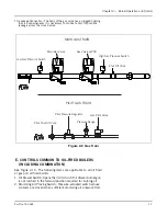
Chapter 2 — Burner Operation and Control
Part No. 750-184
2-11
7. Terminal Block
8. Fuel Oil Strainer (Not Shown): Prevents foreign matter from
entering the burner system.
9. Gas Pilot: See Section D of Chapter 2 for description of the
various components.
10.Light Oil Pilot Valve (Not Shown): When a light oil pilot is
furnished, a solenoid valve is provided to control flow of fuel to
the pilot nozzle. It is energized through programmer contacts. It
is deenergized to shut off pilot fuel flow after main flame is
ignited and established.
11.Back Pressure Orifice: A restriction located in the oil return line
immediately downstream of the fuel oil controller to create back
pressure (100 and 200 series only).`
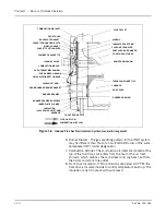
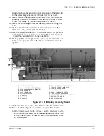
12.Air Pump Module Assembly (Figure 2-13, 2-14): Provides the
compressed air required to atomize the fuel oil for proper
combustion. The CB-LE air pump module is started
automatically by the programmer’s sequence. It includes
components described A-H.
A.
Air Pump Motor: Drives the air pump and an air cooling fan. The
motor is started and stopped simultaneously with the forced draft
fan motor.
B. Air Pump: Provides air for atomization of the fuel oil.
C. Air Filter: The filter cleans the air supply prior to entering air
pump.
D. Check Valve: Prevents lubricating oil and compressed air from
surging back through the pump and air filter when the pump
stops.
E.
Air-Oil Receiver Tank: Holds a supply of oil for lubricating the air
pump. The receiver tank also separates lube oil from the
atomizing air before delivery to nozzle.
F.
Lube Oil Level Sight Glass: Indicates the level of lubricating oil in
the air-oil receiver tank.
Figure 2-13
Belt Driven Air Pump
(Model CB-OS
)
AIR PUMP
DRIVE BELT
HOUSING
AIR
-
OIL
LUBE OIL LEVEL
SIGHT GLASS
TANK
RECEIVER
AIR FILTER
AIR INTAKE
CONTROL VALVE
A
B
C
D
E
F
H
A
.
AIR
PUMP
MOTOR
B
.
AIR
PUMP
C
.
AIR
FILTER
D
.
CHECK
VALVE
E
.
AIR
-
OIL
RECEIVER
TANK
F
.
LUBE
OIL
LEVEL
SIGHT
GLASS
G
.
LUBE
OIL
COOLING
COIL
G
Figure 2-14 Air Pump, CB-LE
Summary of Contents for CB Ohio Special 100 HP
Page 2: ...ii ...
Page 8: ...viii ...
Page 42: ...Chapter 2 Burner Operation and Control 2 22 Part No 750 184 ...
Page 116: ...Chapter 6 Adjustment Procedures 6 28 Part No 750 184 ...
Page 126: ...Chapter 8 Inspection and Maintenance 8 6 Part No 750 184 ...
Page 153: ...Chapter 9 Parts Part No 750 184 9 3 Insulated Front Head Model CB LE ...
Page 154: ...Chapter 9 Parts 9 4 Part No 750 184 Insulated Front Head Interior Model CB LE ...
Page 155: ...Chapter 9 Parts Part No 750 184 9 5 Insulated Inner Door Model CB OS ...
Page 156: ...Chapter 9 Parts 9 6 Part No 750 184 Insulated Rear Head CB LE ...
Page 157: ...Chapter 9 Parts Part No 750 184 9 7 Insulated Rear Head CB LE ...
Page 158: ...Chapter 9 Parts 9 8 Part No 750 184 Insulated Rear Head CB OS ...
Page 159: ...Chapter 9 Parts Part No 750 184 9 9 Dry Oven Model CB LE ...
Page 161: ...Chapter 9 Parts Part No 750 184 9 11 Motor Impeller Model CB LE ...
Page 162: ...Chapter 9 Parts 9 12 Part No 750 184 Front Head Linkage ...
Page 170: ...Chapter 9 Parts 9 20 Part No 750 184 Control Cabinet Hawk ICS ...
Page 171: ...Chapter 9 Parts Part No 750 184 9 21 Control Panel Standard ...
Page 172: ...Chapter 9 Parts 9 22 Part No 750 184 Entrance Box ...
Page 173: ...Chapter 9 Parts Part No 750 184 9 23 Front Head Electrical CB LE ...
Page 174: ...Chapter 9 Parts 9 24 Part No 750 184 Front Head Electrical CB LE ...
Page 175: ...Chapter 9 Parts Part No 750 184 9 25 Front Head Electrical CB OS ...
Page 176: ...Chapter 9 Parts 9 26 Part No 750 184 Front Head Electrical CB OS ...
Page 179: ...Chapter 9 Parts Part No 750 184 9 29 Heavy Oil Piping 60 Steam CB LE ...
Page 180: ...Chapter 9 Parts 9 30 Part No 750 184 Heavy Oil Piping 60 Steam CB LE SEE TABLE NEXT PAGE ...
Page 181: ...Chapter 9 Parts Part No 750 184 9 31 Common Oil Parts Heavy Oil ...
Page 182: ...Chapter 9 Parts 9 32 Part No 750 184 Side Mounted Air Compressor Piping ...
Page 183: ...Chapter 9 Parts Part No 750 184 9 33 Air Compressor Piping CB OS ...
Page 185: ...Chapter 9 Parts Part No 750 184 9 35 Light Oil Piping ...
Page 186: ...Chapter 9 Parts 9 36 Part No 750 184 Light Oil Air Piping Front Head ...
Page 187: ...Chapter 9 Parts Part No 750 184 9 37 Light Oil Air Piping Front Head PAGE 9 31 ...
Page 191: ...Chapter 9 Parts Part No 750 184 9 41 Gas Train 125 150 HP ...
Page 193: ...Chapter 9 Parts Part No 750 184 9 43 Gas Train 200 HP ...
Page 195: ...Chapter 9 Parts Part No 750 184 9 45 Steam Pressure Controls ...
Page 196: ...Chapter 9 Parts 9 46 Part No 750 184 Hot Water Temperature Controls ...
Page 197: ...Chapter 9 Parts Part No 750 184 9 47 Water Column ...
Page 198: ...Chapter 9 Parts 9 48 Part No 750 184 Water Column ...
Page 199: ...Chapter 9 Parts Part No 750 184 9 49 Fireside Gaskets CB LE ...
Page 200: ...Chapter 9 Parts 9 50 Part No 750 184 Fireside Gaskets CB OS ...

