Chapter 6 — Adjustment Procedures
Part No. 750-184
6-13
tions, refer to the trouble shooting section in the technical bulle-
tin.
P. GAS PRESSURE AND FLOW INFORMATION
Because of variables in both the properties of gas and the supply
system, it will be necessary to regulate the pressure of the gas to a
level that produces a steady, dependable flame that yields highest
combustion efficiency at rated performance yet prevents overfiring.
Once the optimum pressure has been established, it should be
recorded and periodic checks made to verify that the regulator is
holding the pressure at this level. Occasional modification in fuel
composition or pressure by the supplier may, at times, require
readjustment to return the burner to peak efficiency.
Pressure
The gas supplied must provide not only the quantity of gas
demanded by the unit, but must also be at a pressure high enough
to overcome the pressure loss due to the frictional resistance
imposed by the burner system and the control valves.
The pressure required at the entrance to the burner gas train for
rated boiler output is termed “net regulated pressure.” The gas
pressure regulator must be adjusted to achieve the pressure to
assure full input.
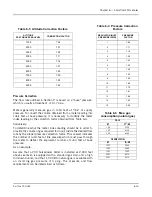
The pressure requirement varies with boiler size, altitude, and type
of gas train. See Tables 6-1 to 6-3.
The pressures listed are based on 1000 Btu/cu-ft natural gas at
elevations up to 700 feet above sea level. For installation at higher
altitudes, multiply the selected pressure by the proper factor from
Table 6-5.
Gas Flow
The volume of gas flow is measured in terms of cubic feet and is
determined by a meter reading. The gas flow rate required for
maximum boiler output depends on the heating value (Btu/cu-ft) of
the gas supplied and boiler efficiency. The supplying utility can
provide precise information on fuel heating value.
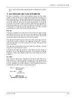
INPUT = OUTPUT x 100%
EFFICIENCY
GAS FLOW = INPUT
GAS BTU’s/Ft
3
=
OUTPUT x 100
EFFICIENCY x GAS BTU’s/Ft
3
Summary of Contents for CB Ohio Special 100 HP
Page 2: ...ii ...
Page 8: ...viii ...
Page 42: ...Chapter 2 Burner Operation and Control 2 22 Part No 750 184 ...
Page 116: ...Chapter 6 Adjustment Procedures 6 28 Part No 750 184 ...
Page 126: ...Chapter 8 Inspection and Maintenance 8 6 Part No 750 184 ...
Page 153: ...Chapter 9 Parts Part No 750 184 9 3 Insulated Front Head Model CB LE ...
Page 154: ...Chapter 9 Parts 9 4 Part No 750 184 Insulated Front Head Interior Model CB LE ...
Page 155: ...Chapter 9 Parts Part No 750 184 9 5 Insulated Inner Door Model CB OS ...
Page 156: ...Chapter 9 Parts 9 6 Part No 750 184 Insulated Rear Head CB LE ...
Page 157: ...Chapter 9 Parts Part No 750 184 9 7 Insulated Rear Head CB LE ...
Page 158: ...Chapter 9 Parts 9 8 Part No 750 184 Insulated Rear Head CB OS ...
Page 159: ...Chapter 9 Parts Part No 750 184 9 9 Dry Oven Model CB LE ...
Page 161: ...Chapter 9 Parts Part No 750 184 9 11 Motor Impeller Model CB LE ...
Page 162: ...Chapter 9 Parts 9 12 Part No 750 184 Front Head Linkage ...
Page 170: ...Chapter 9 Parts 9 20 Part No 750 184 Control Cabinet Hawk ICS ...
Page 171: ...Chapter 9 Parts Part No 750 184 9 21 Control Panel Standard ...
Page 172: ...Chapter 9 Parts 9 22 Part No 750 184 Entrance Box ...
Page 173: ...Chapter 9 Parts Part No 750 184 9 23 Front Head Electrical CB LE ...
Page 174: ...Chapter 9 Parts 9 24 Part No 750 184 Front Head Electrical CB LE ...
Page 175: ...Chapter 9 Parts Part No 750 184 9 25 Front Head Electrical CB OS ...
Page 176: ...Chapter 9 Parts 9 26 Part No 750 184 Front Head Electrical CB OS ...
Page 179: ...Chapter 9 Parts Part No 750 184 9 29 Heavy Oil Piping 60 Steam CB LE ...
Page 180: ...Chapter 9 Parts 9 30 Part No 750 184 Heavy Oil Piping 60 Steam CB LE SEE TABLE NEXT PAGE ...
Page 181: ...Chapter 9 Parts Part No 750 184 9 31 Common Oil Parts Heavy Oil ...
Page 182: ...Chapter 9 Parts 9 32 Part No 750 184 Side Mounted Air Compressor Piping ...
Page 183: ...Chapter 9 Parts Part No 750 184 9 33 Air Compressor Piping CB OS ...
Page 185: ...Chapter 9 Parts Part No 750 184 9 35 Light Oil Piping ...
Page 186: ...Chapter 9 Parts 9 36 Part No 750 184 Light Oil Air Piping Front Head ...
Page 187: ...Chapter 9 Parts Part No 750 184 9 37 Light Oil Air Piping Front Head PAGE 9 31 ...
Page 191: ...Chapter 9 Parts Part No 750 184 9 41 Gas Train 125 150 HP ...
Page 193: ...Chapter 9 Parts Part No 750 184 9 43 Gas Train 200 HP ...
Page 195: ...Chapter 9 Parts Part No 750 184 9 45 Steam Pressure Controls ...
Page 196: ...Chapter 9 Parts 9 46 Part No 750 184 Hot Water Temperature Controls ...
Page 197: ...Chapter 9 Parts Part No 750 184 9 47 Water Column ...
Page 198: ...Chapter 9 Parts 9 48 Part No 750 184 Water Column ...
Page 199: ...Chapter 9 Parts Part No 750 184 9 49 Fireside Gaskets CB LE ...
Page 200: ...Chapter 9 Parts 9 50 Part No 750 184 Fireside Gaskets CB OS ...


