Model FLE Assembly
Pressure Vessel Assembly
750-192
2-5
The pressure vessel is assembled in the factory,
hydro tested and stamped (Figure 2-9). For
convenient assembly, prior to disassembly and
crating, all the tubes are color coded and numbered
with the corresponding numbers on the drums. In
the process of staging the components for assembly,
there could be circumstances where the individual
tubes have to be hand carried to the assembly site.
If the assemblers are unsure of the correct tube
placement, verify the correct location for each tube
by measuring the second, third or forth pass gap
and cross reference with tube location figures in this
chapter.
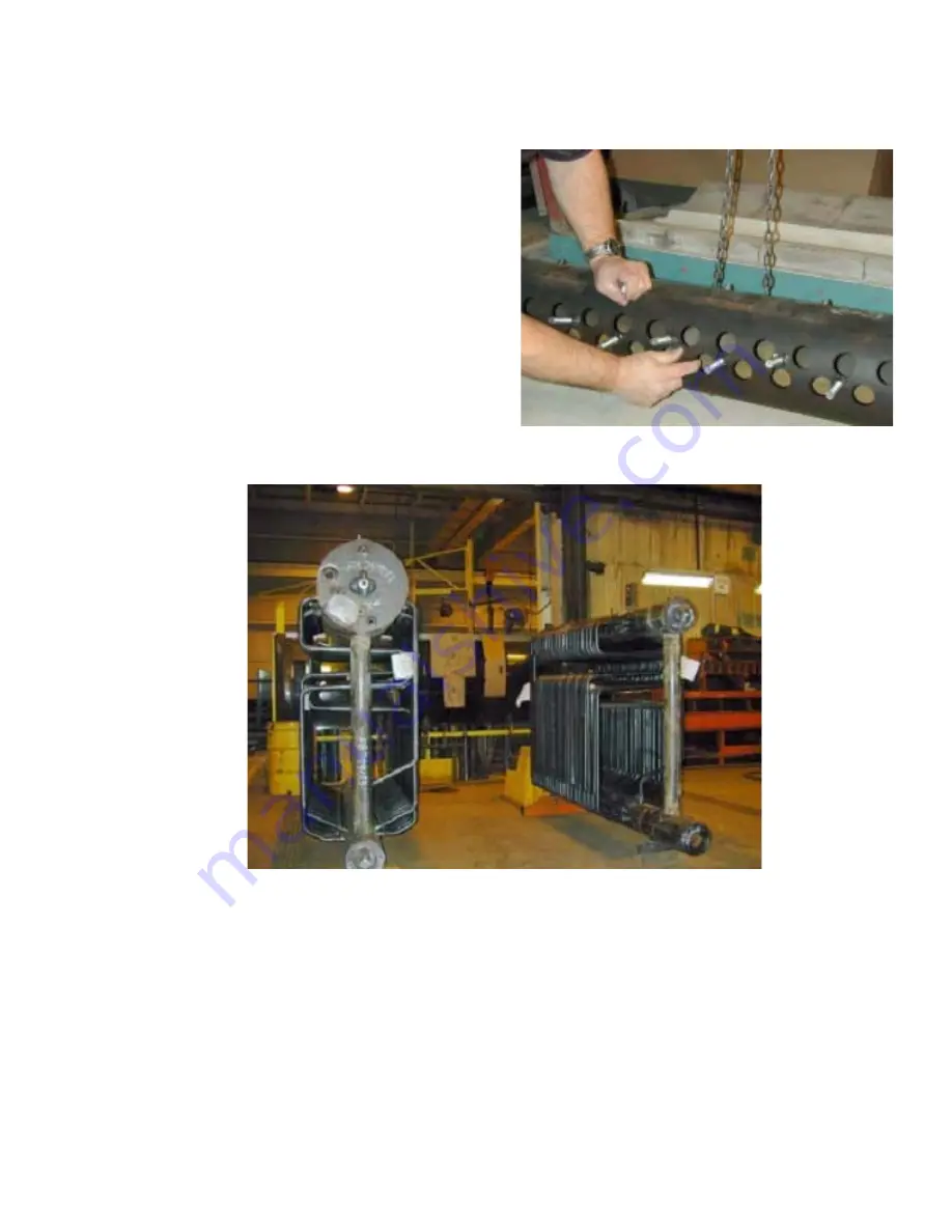
Figure 2-8. Use caution when inspecting drum holes
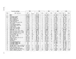
Figure 2-9. A steam vessel (left) and a hot water vessel (right)
Summary of Contents for FLE
Page 1: ...Model FLE Assembly Instructions 750 192 07 09 Field Erectable Flexible Watertube Boiler ...
Page 4: ...iv Notes ...
Page 8: ...viii ...
Page 16: ...General Description Model FLE Assembly 1 8 750 192 ...
Page 34: ...3 2 750 192 Figure 3 1 Typical Hot Water Flextube Casing ...
Page 36: ...3 4 750 192 Figure 3 2 Typical Low Pressure Steam Flextube Casing ...
Page 38: ...3 6 750 192 Figure 3 3 Typical High Pressure Steam Flextube Casing ...
Page 56: ...Casing Assembly Model FLE Assembly 3 24 750 192 ...
Page 58: ...750 192 4 2 Figure 4 2 Fuel Train Components ...
Page 60: ...4 4 750 192 Figure 4 5 Typical conduit layout ProFire burner on a hot water Flextube boiler ...
Page 61: ...750 192 4 5 Figure 4 6 Typical conduit layout ProFire burner on a steam Flextube boiler ...
Page 62: ...4 6 750 192 Figure 4 7 Nameplate locations hot water boiler ...
Page 63: ...750 192 4 7 Figure 4 8 Nameplate locations steam boiler ...
Page 64: ...e mail info cleaverbrooks com Web Address http www cleaverbrooks com ...


