background image

Manual Part No. 750-204

07/2019

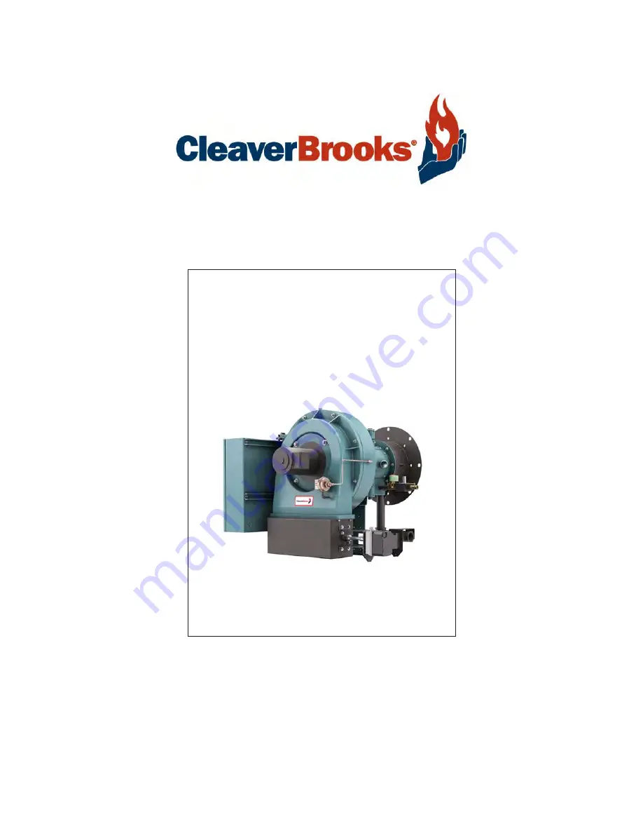
 ProFire D/LND

Burners

Gas/Oil/Dual Fuel

Installation, Operation, Service, and Parts

Table Of Contents

Summary of Contents for ProFire D Series

Page 1: ...Manual Part No 750 204 07 2019 ProFire D LND Burners Gas Oil Dual Fuel Installation Operation Service and Parts Table Of Contents...

Page 2: ......

Page 3: ...PROFIRE D LND Installation Operation and Service Manual Manual Number 750 204 Release Date July 2019...

Page 4: ...d No part of this document may be reproduced stored in a retrieval system or transmitted in any form or by any means without the prior written consent of Cleaver Brooks Cleaver Brooks 351 21st Street...

Page 5: ...applicable local state or provincial instal lation requirements including the National Electrical Code NEC and Associated Insurance Underwriters Where applicable the Canadian Gas Association CGA B149...

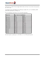
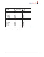
Page 6: ...se oil or any oil containing gasoline Gas input based on natural gass at 1 000 Btu cu ft and 0 60 specific gravity Burner Size Max Burner Gas Input MBTU hr 60hz 50hz 42 S or P 4 200 3 360 54 S or P 5...

Page 7: ...rner Oil Input U S G P H 60hz 50hz 42 S or P 30 24 54 S or P 39 30 63 S or P 47 38 84 S or P 60 53 105 S or P 75 60 145 S or P 107 90 175 S or P 125 105 210 S or P 150 120 252 S or P 180 150 300 S or...

Page 8: ......

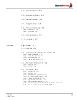
Page 9: ...Air Atomizing 1 5 1 8 1 3 Way Solenoid Valve 1 5 1 8 2 Nozzle Assembly 1 5 1 8 3 Burner Mounted Trim Heater 1 6 1 8 4 Oil Strainer 1 6 1 8 5 Atomizing Air Proving Switch 1 6 1 8 6 Air Lube Oil Tank 1...

Page 10: ...p 2 8 2 9 Oil Loop Heater 2 8 2 10 Burner Mounted Trim Heater 2 8 2 11 Back Pressure Valve 2 8 2 12 Gas Piping 2 9 2 13 Installation Checklist 2 9 CHAPTER 3 Operation 3 1 3 1 Preparations for Starting...

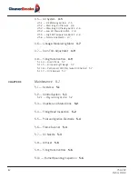
Page 11: ...1 Stack Temperature 4 1 4 2 2 Smoke Measurement 4 2 4 2 3 Gas Adjustments 4 2 4 2 4 Fuel Oil Adjustments 4 2 4 3 Electrical Interference Test 4 2 4 3 1 Gas Fired 4 2 4 3 2 Oil Fired 4 2 4 4 Gas System...

Page 12: ...justment 4 9 4 8 Firing Rate Controls 4 9 5 11 4 Air Oil Tank 5 7 5 11 5 Oil Level Sight Gauge 5 7 5 11 6 Compressor Oil Filter Lube Oil Strainer 5 7 5 11 7 Oil Strainers 5 7 CHAPTER 5 Maintenance 5 1...

Page 13: ...le Line Heater 5 9 5 11 9 Oil Strainers 5 9 5 12 Gas System 5 9 5 12 1 Motorized Main Gas Valves 5 9 5 12 2 Solenoid Valves 5 9 5 13 Electrical System 5 10 5 13 1 Electric Motors 5 1 0 5 14 Extended S...

Page 14: ...ocedures Credit or Replacement Parts 9 2 9 4 Parts Lists and Drawings 9 4 9 4 2 Blast Tube Assembly D42 336 9 4 9 4 2 Blast Tube Assembly D378 420 9 6 9 4 3 Blower Housing Assembly D42 175 9 8 9 4 4 B...

Page 15: ...0 Oil Metering Assembly DL DLG DM DMG42 145 9 41 9 4 21 Oil Metering Assembly DL DLG DM DMG175 420 DE DEG42 420 9 43 9 4 22 Oil Metering Assembly D378 420 9 46 9 4 23 Modulation Standard 9 48 9 4 24 M...

Page 16: ...viii 750 204 Profire D LND...

Page 17: ...wing sections 1 2 Description The Profire D Series oil burners are of the low pressure air atomizing nozzle type Gas burners are of the peripheral mix type All burners feature ignition by spark ignite...

Page 18: ...low the programmer to com plete post purge and shutdown before moving the selector switch to the gas position This will allow the interlock circuit to de energize at either the oil air pump or the com...

Page 19: ...low fire position and opens as the burner drives toward a high fire position Motor Driven Impeller The diameter of the impeller determines available air pressure and the width determines air capacity...

Page 20: ...the levers and the angular position of levers on shafts The lever on the modulating motor shafts actuate the high fire position proving switch 1 7 Firing Head Access to the firing head is provided by...

Page 21: ...parate motor The other system is supplied with a sep arate compressor module for mounting near the burner 1 8 1 3 Way Solenoid Valve Metered oil enters the common port of the 3 way solenoid valve Duri...

Page 22: ...4 5 and 6 fuel oil and is located between the metering pump and the 3 way valve This heater should not be used as a continuous run line heater The heater has an adjustable thermostat and a cold oil lo...

Page 23: ...pistons reciprocate in a rotor assembly turning in a hardened steel sleeve having oil inlet and dis charge slots During each revolution the pistons go through the following cycle 1 Inlet Cycle The pi...

Page 24: ...unit 3 Operation Fuel is delivered to the positive displacement metering pump at 10 to 15 psi Metered oil is deliv ered to the common port of a 3 way solenoid valve for transfer to the burner nozzle...

Page 25: ...750 204 Profire D LND 1 9 1 8 Oil System Air Atomizing FIGURE 1 7 Fuel Oil Metering System Used With Separate Compressor FIGURE 1 8 Integral Compressor Oil Air Metering System...

Page 26: ...mbustion zone pressure The firing rate is regulated by a rotary butterfly type throttling valve at the manifold inlet The valve is actuated by an adjustable linkage from the modulating motor Depending...

Page 27: ...Main Gas Regulator Regulates gas train pressure to specified pressure required at the inlet to the gas train Input is set by main gas pressure regulator adjustment Main Gas Cocks For manual shutoff of...

Page 28: ...nergized unless the combustion air proving switch is closed The low and high gas pressure switches must be closed to prove proper gas pressure A normally open vent valve if required is located between...

Page 29: ...rols remote compressor motor and remotely located fuel valves is fur nished by the installer Automatic over fire draft control or barometric draft regulators are not usually required except where the...

Page 30: ...Installation 2 2 750 204 Profire D LND FIGURE 2 1 Recommended Scotch Marine Chamber Dimensions...

Page 31: ...750 204 Profire D LND 2 3 2 2 Combustion Chamber Construction FIGURE 2 2 Recommended Firebox Watertube Boiler Chamber Dimensions...

Page 32: ...ses under the support leg must be long enough to support the burner when being inserted or withdrawn from the boiler Boilers operating with the combustion pressure above atmospheric pressure must be s...

Page 33: ...oven with Trowleze From inside the furnace ram plastic refractory from the front to the rear parallel to the outside surface of the dry oven 2 5 Separate Compressor Module For oil burners supplied wi...

Page 34: ...e that the supply line is approximately 20 inches or higher above the burner metering pump inlet to help eliminate air problems Above that is an adjust able spring loaded back pressure valve that sets...

Page 35: ...o 2 9 at the end of this chapter No 4 5 Oil Refer to Figures 2 10 to 2 12 at the end of this chapter See Section 2 9 for heater operation No 6 Oil Refer to Figures 2 13 2 14 at the end of this chapter...

Page 36: ...n lift should be as low as possible Maximum suction of 15 Hg vacuum is good practice for either light or heated heavy oil The strainer should be installed in the suc tion line just ahead of the circul...

Page 37: ...regula tions of the supplying utility In the absence of other codes piping should be in accordance with the following prevailing standards National Fuel Gas Code NFPA No 54 ANSI No Z 223 1 For Canada...

Page 38: ...to the burner mounting flange and the boiler front plate Make certain that the operator in charge is properly instructed in the operation and maintenance procedures Before opening the gas shutoff valv...

Page 39: ...750 204 Profire D LND 2 11 2 13 Installation Checklist FIGURE 2 7 Recommended Pipe Size...

Page 40: ...Installation 2 12 750 204 Profire D LND FIGURE 2 8 Recommended Pipe Size...

Page 41: ...SUPPLIED WITH BURNER PRESSURE GAUGE NEEDLE VALVE STRAINER CHECK VALVE VACUUM GAUGE STRAINER GATE VALVE GATE VALVE GATE VALVE PIPING BY OTHERS PIPING BY I C 2 WAY VALVE ON BURNER BACK PRESSURE VALVE SE...

Page 42: ...Installation 2 14 750 204 Profire D LND FIGURE 2 10 Recommended Pipe Size...

Page 43: ...750 204 Profire D LND 2 15 2 13 Installation Checklist FIGURE 2 11 Recommended Pipe Size...

Page 44: ...Installation 2 16 750 204 Profire D LND FIGURE 2 12 Recommended Pipe Size...

Page 45: ...750 204 Profire D LND 2 17 2 13 Installation Checklist FIGURE 2 13 Recommended Pipe Size...

Page 46: ...Installation 2 18 750 204 Profire D LND FIGURE 2 14 Recommended Pipe Size...

Page 47: ...750 204 Profire D LND 2 19 2 13 Installation Checklist FIGURE 2 15 Multiple Boilers Installation Heavy Oil...

Page 48: ...Installation 2 20 750 204 Profire D LND FIGURE 2 16 Typical UL Gas Piping FIGURE 2 17 Typical UL Gas Piping...

Page 49: ...750 204 Profire D LND 2 21 2 13 Installation Checklist FIGURE 2 18 Typical UL Gas Piping FIGURE 2 19 Typical UL Gas Piping...

Page 50: ...Installation 2 22 750 204 Profire D LND...

Page 51: ...voltage on all motors and the control circuit Check the direction or rotation of the motors Open the housing to check the electrode setting refer to Chapter 5 Check the gas pilot pressure at the pilot...

Page 52: ...around the burner should not exceed 25 PSI When the loop around the burner becomes warm gradually close valve No 1 in the bypass line All supply oil will then flow through the burner loop 3 1 2 Oil P...

Page 53: ...main gas shutoff cock remain closed until the programmer has cycled through pre purge and pilot sequences to deter mine that the main gas valve opens Turn the burner switch OFF and let the programmer...

Page 54: ...pilot flame signal pilot turndown and safety switch lockout 3 4 Startup Sequence The programming control sequences the operation of all controls and components through the starting ignition firing and...

Page 55: ...control sequence of operations 3 5 Automatic Shutdown When the limit or operating controls open Fuel valves close The main fuel lamp goes off Flame safeguard timer starts The flame safeguard timer an...

Page 56: ...chamber after each unsuccessful light off attempt Set the gas low fire rate by adjusting the butterfly valve and air linkage When low fire is adjusted shut down the burner Restart several times to be...

Page 57: ...on trial vary according to the type of program mer used During the run cycle burner input is regulated to the load demand by the modulating pressure or temperature control on the boiler The burner wil...

Page 58: ...y shutdown This type of shutdown requires manual reset of the programming control and must be corrected before operation can be resumed An ultraviolet flame sensor electrical spark interference test m...

Page 59: ...nt on Gas and Oil Efficient combustion cannot be properly judged by flame appearance although it may help in making preliminary settings The proper settings of air fuel ratios must be determined by fl...

Page 60: ...15 at high fire 4 3 Electrical Interference Test Prior to putting the burner into service conduct the following test to ascertain that ignition spark will not cause the flame relay to pull in 4 3 1 G...

Page 61: ...size of the pilot flame obtain a proper DC volt or microamp reading of the flame signal The flame safeguard amplifier has a meter jack for this purpose At initial startup and during planned mainte na...

Page 62: ...ressure by adjusting the gas pressure regulator following the manufacturer s direc tions for regulator adjustment When proper gas flow is obtained take a flue gas analysis reading With the high fire a...

Page 63: ...up check that the fire is not burning behind the diffuser If this happens close the secondary valve until this situation is corrected Repeat several times 4 5 Oil System 4 5 1 Oil Metering System Fuel...

Page 64: ...ire is suggested As the firing rate increases the air pressure also increases Air pressure will be less with light oils If any change in atomizing air pressure is made check ignition several times for...

Page 65: ...from starting until proper oil temperature is attained Set it below the oil thermostat setting If the cold oil interlock is set higher than the oil temperature the burner will not run 4 Replace the c...

Page 66: ...osition FIGURE 4 4 High Fire Position The modulating motor will be stopped at the end of its stroke by an internal limit switch Combustion gas analy sis indicates the air to fuel ratio and the degree...

Page 67: ...se from the hex socket end to decrease it a 3 32 hex key is required It will be necessary to cut off the short end of a hex key to approximately 3 8 to adjust the first two socket head setscrews at th...

Page 68: ...tion before adjusting high or intermediate settings Do not alter low fire settings Normally the air control damper will be approximately 1 open in low fire position Excessive opening in low fire can c...

Page 69: ...750 204 Profire D LND 4 11 4 8 Firing Rate Controls FIGURE 4 7 Motor Rotations...

Page 70: ...Adjustments 4 12 750 204 Profire D LND...

Page 71: ...eloping malfunction requiring corrective action 5 2 Control System Most operating controls require very little maintenance beyond regular inspection Examine electrical connec tions Keep the controls c...

Page 72: ...safety check procedures are contained in the manufacturer s bulletin 5 3 Impeller and Stator Cone Proper clearance between the impeller and the inlet housing and between the impeller and stator cone i...

Page 73: ...ing Head Inspection 5 The oil nozzle should be inspected periodically depending on the grade of oil burned and the cleanliness of the environment FIGURE 5 2 Firing Head Assembly Dual Manifold FIGURE 5...

Page 74: ...essful burner operation requires use of the proper style nozzle tip and keeping the orifice clean Standard nozzle tips furnished on the burners are of a special emulsifying type which delivers a spray...

Page 75: ...e To insure proper atomizing the tip must be screwed in tightly with the swirler seating spring pressing the swirler tight against the nozzle tip Turn the swirler a few times to be sure it fits snugly...

Page 76: ...mpt to drive the diffuser back along the blast tube with anything other than a small block of wood tapped against the diffuser s outer edge 5 When reinstalling be sure the diffuser is centered with th...

Page 77: ...w ing 1 See that the oil is at a sufficient level in both the fuel oil tank and the air oil tank on the burner 2 Make sure all valves between the fuel oil tank and the burner are open 3 Be sure the oi...

Page 78: ...or cracked replace it 5 11 4 Air Cleaner Never operate the compressor without the air cleaner in place The cleaner should be cleaned at regular inter vals The correct oil level must be maintained in t...

Page 79: ...creen should be removed and cleaned thoroughly by immersing it in solvent and blowing it dry with compressed air Light oil strainers should be cleaned each month Heavy oil strainers should be checked...

Page 80: ...nd at least once a year thereafter check the motor current with a meter while the burner is in high fire position If the reading exceeds the nameplate rating plus service factor determine the cause an...

Page 81: ...iming Record in log Flame Signal Strength Controls Operator Read and log the flame signal for both pilot and main flame Notify Service if readings are very high very low or fluctuating Linkages Operat...

Page 82: ...Maintenance 5 12 750 204 Profire D LND...

Page 83: ...not be readily apparent The program relay has the capability to self diagnose and to display a code or message that indicates the failure condition Refer to the control bulletin for specifics and sug...

Page 84: ...ion 2 Turn the fuel selector switch to the OFF position 3 Shut off the main manual fuel shutoff valves on the fuel supply line 4 The unit can also be shut down with the main electrical power disconnec...

Page 85: ...switches d Check burner air proving switch and high fire limit switch e Heavy oil fired unit oil temperature below minimum settings 4 Fuel valve interlock circuit not completed a Fuel valve auxiliary...

Page 86: ...ff by obstruction closed valve or loss of suction b Supply pump inoperative c No fuel d Main oil valve inoperative e Check oil nozzle gun and lines 4 Flame detector defective sight tube obstructed or...

Page 87: ...the running interlock circuit 7 Improper air fuel ratio lean fire a Slipping linkage b Damper stuck open c Fluctuating fuel supply Temporary obstruction in the fuel line Temporary drop in gas pressure...

Page 88: ...Troubleshooting 6 6 750 204 Profire D LND...

Page 89: ...HAPTER 7 Accessories 7 1 Overview The D Series burners are available with a wide selection of accessories This section will cover some of the most popular accessories 7 2 Steam Atomizing System FIGURE...

Page 90: ...30 PSI on the discharge side of the regulator While the unit is purging screw in and adjust the nee dle valve to have 10 15 PSI in low fire Install a pressure gauge to monitor the pressure One or two...

Page 91: ...air pressure with the regulator and fine tune with the needle valve to have 10 15 psi on low fire Refer to Chapter 4 to setup the burner FIGURE 7 3 Plant Air System Top Loaded with Air FROM AIR SUPPL...

Page 92: ...Loaded with Oil WIRE TO FLAME SAFEGUARD BLOWER MOTOR TERMINAL FROM AIR SUPPLY AIR FLOW OIL PRESSURE DOWN STREAM OF OIL METERING VALVE NOZZLE PRESSURE TO TOP LOAD AIR PRESSURE REGULATING VALVE NOTE 1 A...

Page 93: ...with input rated at 21 000 MBtu per hour and NOx performance of less than 30 ppm LNDLG 252P 20 indicates a gas and oil burner with input rated at 16 800 MBtu per hour and NOx perfor mance of less tha...

Page 94: ...rner Size Max Burner Gas Input MBTU hr 30 ppm 20 ppm 42 P 3 360 54 P 4 200 3 360 63 P 5 250 4 200 84 S 6 300 5 250 84 P 7 350 6 300 105 P 8 400 7 350 145 S 10 500 8 400 145 P 12 600 10 500 175 P 14 70...

Page 95: ...t piping should be covered with a minimum of 2 of insulation and supported as required The following controls are used in the FGR duct for safe operation of the system Burner Size Max Burner Oil Input...

Page 96: ...15 seconds Proof of closure for the shutoff valve is provided by and auxiliary switch in the modutrol motor The modutrol motor has a maximum temperature rating of 150 F This valve should never be mou...

Page 97: ...the lever hub the less distance the rod and control valve blade will travel FIGURE 8 3 FGR Control Valve and Air FGR Damper 8 5 Air FGR Damper Assembly The air FGR damper regulates the volume of comb...

Page 98: ...Flue Gas Recirculation 8 6 750 204 Profire D LND FIGURE 8 4 FGR Piping and Valve Sizes...

Page 99: ...e the set point the interlock stack temperature rises above the set point the interlock closes and allows the burner to modulate 8 8 20 PPM Design The 20 ppm design features a dual gas manifold Each z...

Page 100: ...Flue Gas Recirculation 8 8 750 204 Profire D LND FIGURE 8 6 20 PPM Head Assembly...

Page 101: ...section does not include such common hardware items as nuts washers electrical parts copper tub ing flare fittings and pipe Items such as these can be readily purchased locally The following parts are...

Page 102: ...is to be issued 2 Once an RGA number has been issued the item may be returned You will have thirty 30 days from the RGA date of issue to return the item After the thirty days there will be a 10 handli...

Page 103: ...Repairs Being Made at the Customer s Expense Marathon Electric Electric Motors Warranty Repair Procedure The following procedure must be used for proper replacement and or repair of Marathon Electric...

Page 104: ...Parts Lists and Drawings 9 4 750 204 Profire D LND 9 4 Parts Lists and Drawings 9 4 2 Blast Tube Assembly D42 336...

Page 105: ...1 40 382 Housing Assembly Firing Head 1 40 380 Housing Assembly Firing Head 1 1 1 40 410 Housing Assembly Firing Head 1 4 8 1025 Bracket Safety Interlock Switch 1 1 1 1 1 1 1 1 1 1 1 1 5 836 301 Swit...

Page 106: ...Parts Lists and Drawings 9 6 750 204 Profire D LND 9 4 2 Blast Tube Assembly D378 420...

Page 107: ...2 psi 1 1 1 1 3 40 380 Housing Assembly Firing Head 1 40 410 Housing Assembly Firing Head 1 40 402 Housing Assembly Firing Head 1 1 4 8 1018 Bracket 1 1 1 1 5 836 301 Switch Safety Interlock 1 1 1 1 6...

Page 108: ...Parts Lists and Drawings 9 8 750 204 Profire D LND 9 4 3 Blower Housing Assembly D42 175...

Page 109: ...1 1 4 Shaft P P 192 304 Impeller Assembly 19 1 4 O D X 1 7 32 Wide X 1 3 4 Shaft P S 192 310 Impeller Assembly 20 O D X 1 19 32 Wide X 1 3 8 Shaft S 192 303 Impeller Assembly 21 O D X 1 3 32 Wide X 1...

Page 110: ...Parts Lists and Drawings 9 10 750 204 Profire D LND 9 4 4 Blower Housing Assembly D210 336...

Page 111: ...D X 2 5 8 Wide X 1 5 8 Shaft S P 192 306 Impeller Assembly 25 1 2 O D X 3 9 32 Wide X 1 5 8 Shaft 1 1 7 869 185 Nut Hex Lock 1 3 8 12 UNF 1 1 1 1 1 8 152 17 Pad Blower Motor MTG 2 1 4 O D X 1 2 I D X...

Page 112: ...Parts Lists and Drawings 9 12 750 204 Profire D LND 9 4 5 Blower Housing Assembly D378 420...

Page 113: ...varies 1 1 6 192 327 Impeller Assembly 1 1 7 869 185 Nut Hex Lock 1 3 8 12 UNF 1 1 8 152 17 Pad Blower Motor Mounting 1 1 9 836 336 Switch Air Pressure 1 1 10 85 892 Support Assembly Damper to Motor 1...

Page 114: ...Parts Lists and Drawings 9 14 750 204 Profire D LND 9 4 6 Compressor Set D42 145...

Page 115: ...Bushing Oil Filter 1 1 1 1 1 1 9 843 106 Filter Oil 1 1 1 1 1 1 10 3 361 Base Assembly Compressor Set 1 1 1 1 1 1 11 809 220 Belt V 1 1 1 1 1 1 12 921 526 Sheave 3 45 P D X 5 8 Bore 1B Groove 1 1 1 1...

Page 116: ...Parts Lists and Drawings 9 16 750 204 Profire D LND 9 4 7 Compressor Set D175 336...

Page 117: ...ove 1 1 921 528 Sheave 3 85 P D X 7 8 Bore 1B Groove 1 1 1 1 13 921 524 Sheave 7 1 P D X 1 9 16 Dia 1 1 1 1 14 810 70 Bushing Split Taper 1 Bore X 1 9 16 Dia 1 1 1 1 15 74 516 Shaft Cooling Fan Mounti...

Page 118: ...Parts Lists and Drawings 9 18 750 204 Profire D LND 9 4 8 Compressor Set D378 420...

Page 119: ...Mounting Base 1 1 15 3 377 Compressor Base 1 1 16 35 438 Compressor Shaft End Guard 1 1 17 923 112 Air Filter 1 1 18 940 1281 1 1 2 NPT Horizontal Check Valve 1 1 19 843 106 Oil Filter 1 1 20 10 315 O...

Page 120: ...Parts Lists and Drawings 9 20 750 204 Profire D LND 9 4 9 Control Package Fireye...

Page 121: ...l Autochecking Infrared 1 1 1 1 1 1 1 1 1 1 832 918 Amplifier Ultra Violet 1 1 1 1 1 1 1 1 1 1 4 833 1018 Base Controller 1 1 1 1 1 1 1 1 1 1 5 833 1337 Chassis E110 1 1 1 1 1 1 1 1 1 1 Fireye Control...

Page 122: ...Parts Lists and Drawings 9 22 750 204 Profire D LND 9 4 10 Control Package Honeywell...

Page 123: ...lifier Ultra Violet 3 Second 1 1 1 1 1 1 1 1 1 1 5 832 1070 Timer 30 Second 1 1 1 1 1 1 1 1 1 1 832 1065 Timer 60 Second 1 1 1 1 1 1 1 1 1 1 832 1066 Timer 90 Second 1 1 1 1 1 1 1 1 1 1 Honeywell Cont...

Page 124: ...Parts Lists and Drawings 9 24 750 204 Profire D LND 9 4 11 Damper Assembly D42 420...

Page 125: ...141 Arm Linkage Assembly 1 1 1 1 1 1 1 2 259 Arm Linkage Assembly 1 1 1 6 807 335 Bearing Flanged 2 PT Damper Shaft 3 4 2 2 2 2 2 807 333 Bearing Square 4 PT Damper Shaft 3 4 2 2 2 2 2 7 18 149 Collar...

Page 126: ...Parts Lists and Drawings 9 26 750 204 Profire D LND 9 4 12 Damper Assembly LND42 420...

Page 127: ...ch 1 1 1 1 1 1 1 1 1 1 4 836 301 Switch High Fire Interlock 1 1 1 1 1 1 1 1 1 1 5 2 184 Arm Linkage Assembly 1 1 1 1 1 1 1 1 1 1 6 807 335 Bearing Flanged 2 PT Damper Shaft 3 4 2 2 2 2 2 807 333 Beari...

Page 128: ...Parts Lists and Drawings 9 28 750 204 Profire D LND 9 4 13 Drawer Assembly D42 63...

Page 129: ...9 Nozzle Assembly Models DG DM DMG 1 528 13 Nozzle Assembly Models DG DM DMG 1 528 29 Nozzle Assembly Models DG DM DMG 1 528 47 Nozzle Assembly Models DE DEG 1 1 1 4 817 varies 1 1 1 5 90 228 Tube Sca...

Page 130: ...Parts Lists and Drawings 9 30 750 204 Profire D LND 9 4 14 Drawer Assembly D84 145...

Page 131: ...D X 082 All Models Except DE DEG 1 82 128 Spring Nozzle Compression 732 FL X 405 I D X 092 Models DE DEG 1 9 528 13 Nozzle Assembly Models DL DLG 1 528 36 Nozzle Assembly Models DL DLG 1 528 34 Nozzl...

Page 132: ...Parts Lists and Drawings 9 32 750 204 Profire D LND 9 4 15 Drawer Assembly D175 336...

Page 133: ...D X 1 All Models 1 1 1 1 1 1 9 528 26 Nozzle Assembly All Models 1 1 1 528 30 Nozzle Assembly All Models 1 1 1 10 275 190 Diffuser Assembly Air Standard All Models 1 275 189 Diffuser Assembly Air Stan...

Page 134: ...Parts Lists and Drawings 9 34 750 204 Profire D LND 9 4 16 Drawer Assembly D378 420...

Page 135: ...7 196 U Bolt 3 4 Pipe Thd 1 4 20 1 1 8 90 559 Tube Assembly Oil Nozzle Deliver 2 2 9 277 107 Nozzle Body Assembly 2 12 Nozzle Thds All Models 1 1 10 82 121 Spring Nozzle Compression 49 64 F L X 7 I D...

Page 136: ...Parts Lists and Drawings 9 36 750 204 Profire D LND 9 4 17 Firing Head Assembly D42 420...

Page 137: ...Oven Assembly 1 1 279 59 Dry Oven Assembly 1 279 76 Dry Oven Assembly 1 1 279 77 Dry Oven Assembly 1 1 4 42 52 Spud Gas Orifice Protection 312 O D 3 3 3 3 3 4 4 5 5 5 5 940 1192 Valve Gas Butterfly 2...

Page 138: ...ies Quantity Item No Part No Description 42 54 63 84 105 145 1 941 187 Valve Needle Shutoff 1 1 1 1 1 1 2 850 3 Gauge Pressure 0 60 PSI 1 1 1 1 1 1 3 195 256 Tank Assembly Air Oil 350 Cu In 1 1 1 1 1...

Page 139: ...750 204 Profire D LND 9 39 9 4 Parts Lists and Drawings 9 4 19 Oil Heater D42 420...

Page 140: ...aters 1 1 1 4 7 144 U Bolt 3 1 2 I D X 5 Legs Threaded 1 4 20 2 2 2 2 2 2 2 7 144 U Bolt 4 I D X 6 Legs Threaded 1 4 20 2 2 2 5 817 829 Switch Air Oil Pressure 4 12 PSI 1 1 1 1 1 1 1 1 1 1 6 817 620 S...

Page 141: ...750 204 Profire D LND 9 41 9 4 Parts Lists and Drawings 9 4 20 Oil Metering Assembly DL DLG DM DMG42 145...

Page 142: ...r 5 4 Models DM DMG 1 695 92 Meter Compressor Assembly Oil Air 6 4 Models DM DMG 1 12 695 64 Meter Compressor Assembly Oil Air 5 5 Models DM DMG 1 12 695 66 Meter Compressor Assembly Oil Air 7 5 Model...

Page 143: ...750 204 Profire D LND 9 43 9 4 Parts Lists and Drawings 9 4 21 Oil Metering Assembly DL DLG DM DMG175 420 DE DEG42 420...

Page 144: ...y Oil 100L 1 695 82 Metering Head Ass y Oil 125L 1 695 73 Metering Head Ass y OIl 150L 1 695 83 Metering Head Ass y Oil 180L 1 695 74 Metering Head Ass y Oil 200L 1 695 75 Metering Head Ass y Oil 350L...

Page 145: ...ing Drive 5 8 X 5 8 Bore 1 1 5 695 112 Metering Head Assembly Oil 300L 1 1 6 282 13 Stop Ass y Override Metering Head 1 1 7 476 53 Linkage Ass y Limiting Arm 9 Holes 5 16 1 1 8 940 1372 Valve Oil Sole...

Page 146: ...Parts Lists and Drawings 9 46 750 204 Profire D LND 9 4 22 Oil Metering Assembly D378 420...

Page 147: ...embly Metering Head 1 1 4 29 1149 Flange Oil Metering Adaptor 1 1 5 695 112 Metering Head Assembly Oil 300L 1 1 6 282 13 Stop Assembly Override E Style Metering Head 1 1 7 476 53 Linkage Assembly Limi...

Page 148: ...10 309 Bushing Mod Motor Control Arm 9 1 2 LG 1 1 1 1 1 1 1 5 2 184 Arm Linkage 3 4 Shaft X 3 Slot 2 2 2 2 2 2 2 6 2 141 Arm Linkage 3 4 Shaft 7 Holes 1 1 1 1 1 1 1 Standard Modulation Quantity Item...

Page 149: ...1 1 1 1 1 1 5 2 184 Arm Linkage 3 4 Shaft X 3 Slot 2 2 2 2 2 2 2 6 2 141 Arm Linkage 3 4 Shaft 7 Holes 2 2 2 2 2 2 2 7 10 307 Bushing Mod Motor Control Arm 22 LG 1 1 1 1 1 1 1 Standard Modulation Qua...

Page 150: ...16 8 71 24 Screw Spring Fastener 2 2 2 2 2 2 2 2 2 2 9 860 301 Screw Locking Set Kit 16 per kit 1 1 1 1 1 1 1 1 1 1 10 860 299 Screw Set 10 32 X 1 LG Half Dog Point 16 16 16 16 16 16 16 16 16 16 11 3...

Page 151: ...Kit 16 per kit 1 1 1 1 10 860 299 Screw Set 10 32 X 1 LG Half Dog Point 16 16 16 16 11 313 15 Cam Assembly Right Hand 2 2 2 1 12 476 84 Linkage Cam Follower Assembly Gas 1 1 1 1 476 82 Linkage Cam Fo...

Page 152: ...Parts Lists and Drawings 9 52 750 204 Profire D LND 9 4 26 Modulation Cam Trim Low NOx or Left Hand Gas...

Page 153: ...it 1 1 1 1 1 1 1 1 1 1 10 860 299 Screw Set 10 32 X 1 LG Half Dog Point 16 16 16 16 16 16 16 16 16 16 11 313 14 Cam Assembly Left Hand 1 1 1 1 1 1 1 1 1 1 313 15 Cam Assembly Right Hand 2 2 2 2 2 2 2...

Page 154: ...LG Half Dog Point 16 16 16 16 11 313 14 Cam Assembly Left Hand 1 1 1 1 313 15 Cam Assembly Right Hand 2 2 2 2 12 476 84 Linkage Cam Follower Assembly Gas 1 1 1 1 476 82 Linkage Cam Follower Assembly O...

Page 155: ...Room Temp F Operating Limit O2 High Limit CO Operating Control CO PPM Stack Temp Interlock NOx PPM Flame Failure Smoke Bacharach Combustion Air Switch Combustion Eff High Purge Switch Stack Draft W C...

Page 156: ...750 204 Profire D LND...

Page 157: ...equipment Warranty Adjustment Buyer must make claim of any breach of any warranty by written notice to the Company s home office within thirty 30 days of the discovery of any defect The Company agrees...

Page 158: ...Company s liability for breach of implied if any and express warranties representations instructions or defects from any cause in connection with the sale or use of the equipment THE COMPANY SHALL NO...

Page 159: ......

Page 160: ......

Reviews: