Installation
2-4
750-204
Profire D/LND
2.3 — Installation
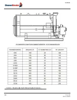
Locate the burner properly. The burner is designed for operation with the blast tube level. Do not tilt the burner
up or excessively downward. Installation of the refractory oven or combustion cone, shipped with the burner, is
shown in Figures 2-3 and 2-4.
FIGURE 2-3.
Firebox and Watertube Burner Mounting Details
Securely support the burner pedestal on the floor or foundation Allow enough clearance at the rear of the burner
to allow the housing to swing open for service and maintenance. Figure 2-2 shows an installation with typical
burner support. Many boilers, including some Scotch Marine types, do not have sufficiently rigid front plates and
require additional support under the burner base. Bases under the support leg must be long enough to support
the burner when being inserted or withdrawn from the boiler. Boilers operating with the combustion pressure
above atmospheric pressure must be sealed to prevent escape of combustion products into the boiler room. The
burner mounting flange is designed to provide for a seal. The face of the boiler and burner flange must be sealed
with the gasket provided with the burner. Carefully place the gasket over the dry oven bolts before it is mounted
onto the burner flange. The I.D. of the dry oven is slightly larger than the blast tube I.D. Make sure the dry oven
and burner blast tube are concentric. Due to bolt hole tolerances, the dry oven may have to be shifted to accom-
plish this. After the dry oven nuts are properly tightened, the burner and dry oven assembly can then be
mounted into the boiler. For maximum safety, it is recommended that boilers not operating under pressure should
also be sealed.
Summary of Contents for ProFire D Series
Page 2: ......
Page 8: ......
Page 16: ...viii 750 204 Profire D LND...
Page 30: ...Installation 2 2 750 204 Profire D LND FIGURE 2 1 Recommended Scotch Marine Chamber Dimensions...
Page 39: ...750 204 Profire D LND 2 11 2 13 Installation Checklist FIGURE 2 7 Recommended Pipe Size...
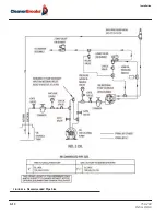
Page 40: ...Installation 2 12 750 204 Profire D LND FIGURE 2 8 Recommended Pipe Size...
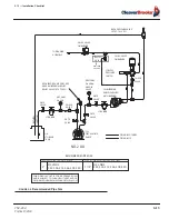
Page 42: ...Installation 2 14 750 204 Profire D LND FIGURE 2 10 Recommended Pipe Size...
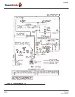
Page 43: ...750 204 Profire D LND 2 15 2 13 Installation Checklist FIGURE 2 11 Recommended Pipe Size...
Page 44: ...Installation 2 16 750 204 Profire D LND FIGURE 2 12 Recommended Pipe Size...
Page 45: ...750 204 Profire D LND 2 17 2 13 Installation Checklist FIGURE 2 13 Recommended Pipe Size...
Page 46: ...Installation 2 18 750 204 Profire D LND FIGURE 2 14 Recommended Pipe Size...
Page 50: ...Installation 2 22 750 204 Profire D LND...
Page 69: ...750 204 Profire D LND 4 11 4 8 Firing Rate Controls FIGURE 4 7 Motor Rotations...
Page 70: ...Adjustments 4 12 750 204 Profire D LND...
Page 82: ...Maintenance 5 12 750 204 Profire D LND...
Page 88: ...Troubleshooting 6 6 750 204 Profire D LND...
Page 98: ...Flue Gas Recirculation 8 6 750 204 Profire D LND FIGURE 8 4 FGR Piping and Valve Sizes...
Page 100: ...Flue Gas Recirculation 8 8 750 204 Profire D LND FIGURE 8 6 20 PPM Head Assembly...
Page 106: ...Parts Lists and Drawings 9 6 750 204 Profire D LND 9 4 2 Blast Tube Assembly D378 420...
Page 108: ...Parts Lists and Drawings 9 8 750 204 Profire D LND 9 4 3 Blower Housing Assembly D42 175...
Page 110: ...Parts Lists and Drawings 9 10 750 204 Profire D LND 9 4 4 Blower Housing Assembly D210 336...
Page 112: ...Parts Lists and Drawings 9 12 750 204 Profire D LND 9 4 5 Blower Housing Assembly D378 420...
Page 114: ...Parts Lists and Drawings 9 14 750 204 Profire D LND 9 4 6 Compressor Set D42 145...
Page 116: ...Parts Lists and Drawings 9 16 750 204 Profire D LND 9 4 7 Compressor Set D175 336...
Page 118: ...Parts Lists and Drawings 9 18 750 204 Profire D LND 9 4 8 Compressor Set D378 420...
Page 120: ...Parts Lists and Drawings 9 20 750 204 Profire D LND 9 4 9 Control Package Fireye...
Page 122: ...Parts Lists and Drawings 9 22 750 204 Profire D LND 9 4 10 Control Package Honeywell...
Page 124: ...Parts Lists and Drawings 9 24 750 204 Profire D LND 9 4 11 Damper Assembly D42 420...
Page 126: ...Parts Lists and Drawings 9 26 750 204 Profire D LND 9 4 12 Damper Assembly LND42 420...
Page 128: ...Parts Lists and Drawings 9 28 750 204 Profire D LND 9 4 13 Drawer Assembly D42 63...
Page 130: ...Parts Lists and Drawings 9 30 750 204 Profire D LND 9 4 14 Drawer Assembly D84 145...
Page 132: ...Parts Lists and Drawings 9 32 750 204 Profire D LND 9 4 15 Drawer Assembly D175 336...
Page 134: ...Parts Lists and Drawings 9 34 750 204 Profire D LND 9 4 16 Drawer Assembly D378 420...
Page 136: ...Parts Lists and Drawings 9 36 750 204 Profire D LND 9 4 17 Firing Head Assembly D42 420...
Page 139: ...750 204 Profire D LND 9 39 9 4 Parts Lists and Drawings 9 4 19 Oil Heater D42 420...
Page 146: ...Parts Lists and Drawings 9 46 750 204 Profire D LND 9 4 22 Oil Metering Assembly D378 420...
Page 156: ...750 204 Profire D LND...
Page 159: ......
Page 160: ......


