Installation
2-6
750-204
Profire D/LND
the blast tube, but piping to the compressor and tank is essentially similar. Copper tubing for the installation is
not supplied with the burner.
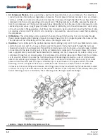
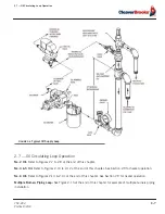
FIGURE 2-5.
Separate Compressor Module
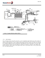
2.6 — Typical Oil Supply Loop
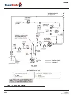
Refer to Figure 2-6. Continuous oil circulation must be supplied to the burner at a rate of 50% greater than the
high fire burning rate. The oil circulating pump should be located as close as possible to the storage tank to keep
suction lines short and minimize suction loss. Pipe line sizes indicated on the following oil piping schematics are
of ample size to reduce pressure losses. If heating of the fuel oil is required, the lines must be large enough to
prevent restriction of flow through any cold spots in the system. Note that the supply line is approximately 20
inches or higher above the burner metering pump inlet to help eliminate air problems. Above that is an adjust-
able, spring-loaded back pressure valve that sets approximately 10 to 15 PSI on the circulating loop. The return
line to the tank is connected at the discharge port of the back pressure valve. Since air rises to the highest point,
it will rise from the supply entrance and pass through the back pressure valve to the return line and on to the
tank. Metered oil is pumped (by the metering pump) to the common port of a 3-way valve. With the 3-way valve
de-energized, the metered oil returns to the tank through the back pressure valve and return line. When the 3-
way valve is energized, metered oil is passed on to the burner oil nozzle and atomized by air from the compres-
sor. The proper strainers, check valves, vacuum and pressure gauges, etc. should be installed as indicated. All
lines should be pressure tested after installation.
Summary of Contents for ProFire D Series
Page 2: ......
Page 8: ......
Page 16: ...viii 750 204 Profire D LND...
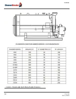
Page 30: ...Installation 2 2 750 204 Profire D LND FIGURE 2 1 Recommended Scotch Marine Chamber Dimensions...
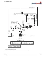
Page 39: ...750 204 Profire D LND 2 11 2 13 Installation Checklist FIGURE 2 7 Recommended Pipe Size...
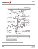
Page 40: ...Installation 2 12 750 204 Profire D LND FIGURE 2 8 Recommended Pipe Size...
Page 42: ...Installation 2 14 750 204 Profire D LND FIGURE 2 10 Recommended Pipe Size...
Page 43: ...750 204 Profire D LND 2 15 2 13 Installation Checklist FIGURE 2 11 Recommended Pipe Size...
Page 44: ...Installation 2 16 750 204 Profire D LND FIGURE 2 12 Recommended Pipe Size...
Page 45: ...750 204 Profire D LND 2 17 2 13 Installation Checklist FIGURE 2 13 Recommended Pipe Size...
Page 46: ...Installation 2 18 750 204 Profire D LND FIGURE 2 14 Recommended Pipe Size...
Page 50: ...Installation 2 22 750 204 Profire D LND...
Page 69: ...750 204 Profire D LND 4 11 4 8 Firing Rate Controls FIGURE 4 7 Motor Rotations...
Page 70: ...Adjustments 4 12 750 204 Profire D LND...
Page 82: ...Maintenance 5 12 750 204 Profire D LND...
Page 88: ...Troubleshooting 6 6 750 204 Profire D LND...
Page 98: ...Flue Gas Recirculation 8 6 750 204 Profire D LND FIGURE 8 4 FGR Piping and Valve Sizes...
Page 100: ...Flue Gas Recirculation 8 8 750 204 Profire D LND FIGURE 8 6 20 PPM Head Assembly...
Page 106: ...Parts Lists and Drawings 9 6 750 204 Profire D LND 9 4 2 Blast Tube Assembly D378 420...
Page 108: ...Parts Lists and Drawings 9 8 750 204 Profire D LND 9 4 3 Blower Housing Assembly D42 175...
Page 110: ...Parts Lists and Drawings 9 10 750 204 Profire D LND 9 4 4 Blower Housing Assembly D210 336...
Page 112: ...Parts Lists and Drawings 9 12 750 204 Profire D LND 9 4 5 Blower Housing Assembly D378 420...
Page 114: ...Parts Lists and Drawings 9 14 750 204 Profire D LND 9 4 6 Compressor Set D42 145...
Page 116: ...Parts Lists and Drawings 9 16 750 204 Profire D LND 9 4 7 Compressor Set D175 336...
Page 118: ...Parts Lists and Drawings 9 18 750 204 Profire D LND 9 4 8 Compressor Set D378 420...
Page 120: ...Parts Lists and Drawings 9 20 750 204 Profire D LND 9 4 9 Control Package Fireye...
Page 122: ...Parts Lists and Drawings 9 22 750 204 Profire D LND 9 4 10 Control Package Honeywell...
Page 124: ...Parts Lists and Drawings 9 24 750 204 Profire D LND 9 4 11 Damper Assembly D42 420...
Page 126: ...Parts Lists and Drawings 9 26 750 204 Profire D LND 9 4 12 Damper Assembly LND42 420...
Page 128: ...Parts Lists and Drawings 9 28 750 204 Profire D LND 9 4 13 Drawer Assembly D42 63...
Page 130: ...Parts Lists and Drawings 9 30 750 204 Profire D LND 9 4 14 Drawer Assembly D84 145...
Page 132: ...Parts Lists and Drawings 9 32 750 204 Profire D LND 9 4 15 Drawer Assembly D175 336...
Page 134: ...Parts Lists and Drawings 9 34 750 204 Profire D LND 9 4 16 Drawer Assembly D378 420...
Page 136: ...Parts Lists and Drawings 9 36 750 204 Profire D LND 9 4 17 Firing Head Assembly D42 420...
Page 139: ...750 204 Profire D LND 9 39 9 4 Parts Lists and Drawings 9 4 19 Oil Heater D42 420...
Page 146: ...Parts Lists and Drawings 9 46 750 204 Profire D LND 9 4 22 Oil Metering Assembly D378 420...
Page 156: ...750 204 Profire D LND...
Page 159: ......
Page 160: ......


