PREFACE
Warning and caution references have been made in this manual and should be adhered to for smooth
operation of the burner.
Model designations are based on the type of fuel(s) to be fired and the amount of furnace pressure to
be overcome. Burner size is based on firing rate (rated input in Btu/hr).
S-Models for up to 1.5” W.C. furnace pressure.
P-Models for up to 4.0” W.C. furnace pressure.
Example: The model number on the nameplate is DLG-252, No. 2 oil and gas burner with input
rated at 25,200 MBtu per hour, against furnace pressures up to 4” W.C. at 60hz.
The installation of a burner shall be in accordance with the regulations of authorities having jurisdic-
tion. The equipment must be installed in accordance with applicable local, state, or provincial instal-
lation requirements including the National Electrical Code (NEC) and Associated Insurance
Underwriters. Where applicable, the Canadian Gas Association (CGA) B149 and Canadian Standard
Association (CSA) B140 and B139 (for oil burners) codes shall prevail. OIl and gas burning equip-
This symbol precedes information which, if disregarded, may result in injury to the user of the burner or
to others.
This symbol precedes information which, if disregarded, may result in damage to the burner.
NOTE:
This symbol precedes information which is vital to the operation or maintenance of the burner.
Model Standards
Fuel-Air Atomization
DG
Gas
DL
#2 Oil
DLG
#2 Oil and Gas
DM
#2-5 Oil
DMG
#2-5 Oil and Gas
DE
#2-6 Oil
DEG
#2-6 Oil and Gas
NOTE:
Firing at higher furnace pressures de-rates the burner by approximately 5% per one half inch of
additional pressure. Consult with the factory.
!
Warning
!
Caution
Summary of Contents for ProFire D Series
Page 2: ......
Page 8: ......
Page 16: ...viii 750 204 Profire D LND...
Page 30: ...Installation 2 2 750 204 Profire D LND FIGURE 2 1 Recommended Scotch Marine Chamber Dimensions...
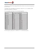
Page 39: ...750 204 Profire D LND 2 11 2 13 Installation Checklist FIGURE 2 7 Recommended Pipe Size...
Page 40: ...Installation 2 12 750 204 Profire D LND FIGURE 2 8 Recommended Pipe Size...
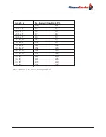
Page 42: ...Installation 2 14 750 204 Profire D LND FIGURE 2 10 Recommended Pipe Size...
Page 43: ...750 204 Profire D LND 2 15 2 13 Installation Checklist FIGURE 2 11 Recommended Pipe Size...
Page 44: ...Installation 2 16 750 204 Profire D LND FIGURE 2 12 Recommended Pipe Size...
Page 45: ...750 204 Profire D LND 2 17 2 13 Installation Checklist FIGURE 2 13 Recommended Pipe Size...
Page 46: ...Installation 2 18 750 204 Profire D LND FIGURE 2 14 Recommended Pipe Size...
Page 50: ...Installation 2 22 750 204 Profire D LND...
Page 69: ...750 204 Profire D LND 4 11 4 8 Firing Rate Controls FIGURE 4 7 Motor Rotations...
Page 70: ...Adjustments 4 12 750 204 Profire D LND...
Page 82: ...Maintenance 5 12 750 204 Profire D LND...
Page 88: ...Troubleshooting 6 6 750 204 Profire D LND...
Page 98: ...Flue Gas Recirculation 8 6 750 204 Profire D LND FIGURE 8 4 FGR Piping and Valve Sizes...
Page 100: ...Flue Gas Recirculation 8 8 750 204 Profire D LND FIGURE 8 6 20 PPM Head Assembly...
Page 106: ...Parts Lists and Drawings 9 6 750 204 Profire D LND 9 4 2 Blast Tube Assembly D378 420...
Page 108: ...Parts Lists and Drawings 9 8 750 204 Profire D LND 9 4 3 Blower Housing Assembly D42 175...
Page 110: ...Parts Lists and Drawings 9 10 750 204 Profire D LND 9 4 4 Blower Housing Assembly D210 336...
Page 112: ...Parts Lists and Drawings 9 12 750 204 Profire D LND 9 4 5 Blower Housing Assembly D378 420...
Page 114: ...Parts Lists and Drawings 9 14 750 204 Profire D LND 9 4 6 Compressor Set D42 145...
Page 116: ...Parts Lists and Drawings 9 16 750 204 Profire D LND 9 4 7 Compressor Set D175 336...
Page 118: ...Parts Lists and Drawings 9 18 750 204 Profire D LND 9 4 8 Compressor Set D378 420...
Page 120: ...Parts Lists and Drawings 9 20 750 204 Profire D LND 9 4 9 Control Package Fireye...
Page 122: ...Parts Lists and Drawings 9 22 750 204 Profire D LND 9 4 10 Control Package Honeywell...
Page 124: ...Parts Lists and Drawings 9 24 750 204 Profire D LND 9 4 11 Damper Assembly D42 420...
Page 126: ...Parts Lists and Drawings 9 26 750 204 Profire D LND 9 4 12 Damper Assembly LND42 420...
Page 128: ...Parts Lists and Drawings 9 28 750 204 Profire D LND 9 4 13 Drawer Assembly D42 63...
Page 130: ...Parts Lists and Drawings 9 30 750 204 Profire D LND 9 4 14 Drawer Assembly D84 145...
Page 132: ...Parts Lists and Drawings 9 32 750 204 Profire D LND 9 4 15 Drawer Assembly D175 336...
Page 134: ...Parts Lists and Drawings 9 34 750 204 Profire D LND 9 4 16 Drawer Assembly D378 420...
Page 136: ...Parts Lists and Drawings 9 36 750 204 Profire D LND 9 4 17 Firing Head Assembly D42 420...
Page 139: ...750 204 Profire D LND 9 39 9 4 Parts Lists and Drawings 9 4 19 Oil Heater D42 420...
Page 146: ...Parts Lists and Drawings 9 46 750 204 Profire D LND 9 4 22 Oil Metering Assembly D378 420...
Page 156: ...750 204 Profire D LND...
Page 159: ......
Page 160: ......


