750-204
Profire D/LND
3-1
CHAPTER 3
Operation
3.1 — Preparations for Starting
When the installation is complete and all electrical, fuel, water and vent stack connections are made, make cer-
tain these connections are tight. The operator should become familiar with the burner, boiler controls, and com-
ponents. Adjustment procedures given in Chapter 4 should be reviewed prior to firing. The wiring diagram should
also be studied along with the operating sequence of the burner programmer.
Read and understand starting instructions before attempting to operate the burner. Before attempting to start the
burner, the following checks must be made:
Component
Description
Burner
Check the electrical power supply to the burner in accordance with the nameplate voltage
on all motors and the control circuit. Check the direction or rotation of the motors. Open
the housing to check the electrode setting (refer to Chapter 5).
Check the gas pilot pressure at the pilot gas regulator. The normal setting is 3” to 5” W.C.
For protection in shipment, the flame safeguard control chassis is shipped unmounted.
Check all screw connections before attaching the flame safeguard chassis to the base.
Screws must be secure to assure low resistance connections. The relay chassis is
mounted on the sub-base with a screw which, when tightened, completes the connection
between the sub-base and chassis contacts. Press the manual reset button to be sure
safety switch contacts are closed.
Check the control linkage for proper movement of the air volume damper and fuel meter-
ing components. This can be done by loosening the linkage at the actuator level and
manipulating it by hand.
Check the air shutter and adjust the low fire setting.
Summary of Contents for ProFire D Series
Page 2: ......
Page 8: ......
Page 16: ...viii 750 204 Profire D LND...
Page 30: ...Installation 2 2 750 204 Profire D LND FIGURE 2 1 Recommended Scotch Marine Chamber Dimensions...
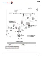
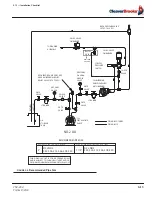
Page 39: ...750 204 Profire D LND 2 11 2 13 Installation Checklist FIGURE 2 7 Recommended Pipe Size...
Page 40: ...Installation 2 12 750 204 Profire D LND FIGURE 2 8 Recommended Pipe Size...
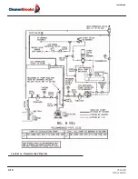
Page 42: ...Installation 2 14 750 204 Profire D LND FIGURE 2 10 Recommended Pipe Size...
Page 43: ...750 204 Profire D LND 2 15 2 13 Installation Checklist FIGURE 2 11 Recommended Pipe Size...
Page 44: ...Installation 2 16 750 204 Profire D LND FIGURE 2 12 Recommended Pipe Size...
Page 45: ...750 204 Profire D LND 2 17 2 13 Installation Checklist FIGURE 2 13 Recommended Pipe Size...
Page 46: ...Installation 2 18 750 204 Profire D LND FIGURE 2 14 Recommended Pipe Size...
Page 50: ...Installation 2 22 750 204 Profire D LND...
Page 69: ...750 204 Profire D LND 4 11 4 8 Firing Rate Controls FIGURE 4 7 Motor Rotations...
Page 70: ...Adjustments 4 12 750 204 Profire D LND...
Page 82: ...Maintenance 5 12 750 204 Profire D LND...
Page 88: ...Troubleshooting 6 6 750 204 Profire D LND...
Page 98: ...Flue Gas Recirculation 8 6 750 204 Profire D LND FIGURE 8 4 FGR Piping and Valve Sizes...
Page 100: ...Flue Gas Recirculation 8 8 750 204 Profire D LND FIGURE 8 6 20 PPM Head Assembly...
Page 106: ...Parts Lists and Drawings 9 6 750 204 Profire D LND 9 4 2 Blast Tube Assembly D378 420...
Page 108: ...Parts Lists and Drawings 9 8 750 204 Profire D LND 9 4 3 Blower Housing Assembly D42 175...
Page 110: ...Parts Lists and Drawings 9 10 750 204 Profire D LND 9 4 4 Blower Housing Assembly D210 336...
Page 112: ...Parts Lists and Drawings 9 12 750 204 Profire D LND 9 4 5 Blower Housing Assembly D378 420...
Page 114: ...Parts Lists and Drawings 9 14 750 204 Profire D LND 9 4 6 Compressor Set D42 145...
Page 116: ...Parts Lists and Drawings 9 16 750 204 Profire D LND 9 4 7 Compressor Set D175 336...
Page 118: ...Parts Lists and Drawings 9 18 750 204 Profire D LND 9 4 8 Compressor Set D378 420...
Page 120: ...Parts Lists and Drawings 9 20 750 204 Profire D LND 9 4 9 Control Package Fireye...
Page 122: ...Parts Lists and Drawings 9 22 750 204 Profire D LND 9 4 10 Control Package Honeywell...
Page 124: ...Parts Lists and Drawings 9 24 750 204 Profire D LND 9 4 11 Damper Assembly D42 420...
Page 126: ...Parts Lists and Drawings 9 26 750 204 Profire D LND 9 4 12 Damper Assembly LND42 420...
Page 128: ...Parts Lists and Drawings 9 28 750 204 Profire D LND 9 4 13 Drawer Assembly D42 63...
Page 130: ...Parts Lists and Drawings 9 30 750 204 Profire D LND 9 4 14 Drawer Assembly D84 145...
Page 132: ...Parts Lists and Drawings 9 32 750 204 Profire D LND 9 4 15 Drawer Assembly D175 336...
Page 134: ...Parts Lists and Drawings 9 34 750 204 Profire D LND 9 4 16 Drawer Assembly D378 420...
Page 136: ...Parts Lists and Drawings 9 36 750 204 Profire D LND 9 4 17 Firing Head Assembly D42 420...
Page 139: ...750 204 Profire D LND 9 39 9 4 Parts Lists and Drawings 9 4 19 Oil Heater D42 420...
Page 146: ...Parts Lists and Drawings 9 46 750 204 Profire D LND 9 4 22 Oil Metering Assembly D378 420...
Page 156: ...750 204 Profire D LND...
Page 159: ......
Page 160: ......


