750-204
Profire D/LND
3-3
3.2 — Electrical Interference Test
heater should be adjusted to give the designed operating temperature. Where the burning characteristics of the
fuel are unknown, the following may be considered as typical:
3.1.4 — Air-Oil Tank (Lube Oil)
Check the lube oil level in the air-oil tank. Inspect oil level regularly. Loss of oil will damage the compressor. Fill
the tank with non detergent SAE30 oil to a level midway up the sight glass. Do not overfill the tank.
For a normal environment use SAE30 oil. For a 32º F and below environment sue SAE 10 oil. Change the oil
every 2000 hours of operation.
3.1.5 — Firing Preparations for Gas Burners
A representative of the gas utility should turn on the gas. Determine by a test gauge upstream of the burner reg-
ulator that sufficient pressure exists at the entrance to the gas train. The gas pressure regulator must be adjusted
to the pressure required and the pressure setting recorded.
On combination fuel models, set the selector switch to “Gas.” On initial startup, it is recommended that the main
gas shutoff cock remain closed until the programmer has cycled through pre-purge and pilot sequences to deter-
mine that the main gas valve opens. Turn the burner switch “OFF” and let the programmer finish its cycle. Check
to see that the gas valve closes tightly. Set the high and low gas pressure switches.
Check for leaks and determine there is adequate gas pressure available at the burner for operating at full capac-
ity. Check with the local utility if necessary. Check gas pressure at the pilot and the main burner. Close the man-
ual gas valve.
3.2 — Electrical Interference Test
Prior to putting the burner into service, conduct the following test to ascertain that the ignition spark will not
cause the flame relay to pull in.
3.2.1 — Gas Fired
1.
Close the pilot and the main line manual gas valves.
2.
Start the burner and at the time of the pilot trial with just the electrical ignition system energized, the flame
relay should not pull in (be energized).
3.
Upon completion of a successful test, proceed with startup procedures.
3.2.2 — Oil Fired
1.
disconnect the electrical power to the burner.
2.
Disconnect the electric oil safety shutoff valve.
3.
Reconnect electric power to the burner.
No. 4
80º - 125º F
No. 5L
115º - 160º F
No. 5H
145º - 180º F
No. 6
180º - 220º F
Summary of Contents for ProFire D Series
Page 2: ......
Page 8: ......
Page 16: ...viii 750 204 Profire D LND...
Page 30: ...Installation 2 2 750 204 Profire D LND FIGURE 2 1 Recommended Scotch Marine Chamber Dimensions...
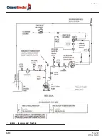
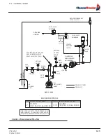
Page 39: ...750 204 Profire D LND 2 11 2 13 Installation Checklist FIGURE 2 7 Recommended Pipe Size...
Page 40: ...Installation 2 12 750 204 Profire D LND FIGURE 2 8 Recommended Pipe Size...
Page 42: ...Installation 2 14 750 204 Profire D LND FIGURE 2 10 Recommended Pipe Size...
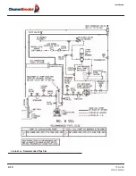
Page 43: ...750 204 Profire D LND 2 15 2 13 Installation Checklist FIGURE 2 11 Recommended Pipe Size...
Page 44: ...Installation 2 16 750 204 Profire D LND FIGURE 2 12 Recommended Pipe Size...
Page 45: ...750 204 Profire D LND 2 17 2 13 Installation Checklist FIGURE 2 13 Recommended Pipe Size...
Page 46: ...Installation 2 18 750 204 Profire D LND FIGURE 2 14 Recommended Pipe Size...
Page 50: ...Installation 2 22 750 204 Profire D LND...
Page 69: ...750 204 Profire D LND 4 11 4 8 Firing Rate Controls FIGURE 4 7 Motor Rotations...
Page 70: ...Adjustments 4 12 750 204 Profire D LND...
Page 82: ...Maintenance 5 12 750 204 Profire D LND...
Page 88: ...Troubleshooting 6 6 750 204 Profire D LND...
Page 98: ...Flue Gas Recirculation 8 6 750 204 Profire D LND FIGURE 8 4 FGR Piping and Valve Sizes...
Page 100: ...Flue Gas Recirculation 8 8 750 204 Profire D LND FIGURE 8 6 20 PPM Head Assembly...
Page 106: ...Parts Lists and Drawings 9 6 750 204 Profire D LND 9 4 2 Blast Tube Assembly D378 420...
Page 108: ...Parts Lists and Drawings 9 8 750 204 Profire D LND 9 4 3 Blower Housing Assembly D42 175...
Page 110: ...Parts Lists and Drawings 9 10 750 204 Profire D LND 9 4 4 Blower Housing Assembly D210 336...
Page 112: ...Parts Lists and Drawings 9 12 750 204 Profire D LND 9 4 5 Blower Housing Assembly D378 420...
Page 114: ...Parts Lists and Drawings 9 14 750 204 Profire D LND 9 4 6 Compressor Set D42 145...
Page 116: ...Parts Lists and Drawings 9 16 750 204 Profire D LND 9 4 7 Compressor Set D175 336...
Page 118: ...Parts Lists and Drawings 9 18 750 204 Profire D LND 9 4 8 Compressor Set D378 420...
Page 120: ...Parts Lists and Drawings 9 20 750 204 Profire D LND 9 4 9 Control Package Fireye...
Page 122: ...Parts Lists and Drawings 9 22 750 204 Profire D LND 9 4 10 Control Package Honeywell...
Page 124: ...Parts Lists and Drawings 9 24 750 204 Profire D LND 9 4 11 Damper Assembly D42 420...
Page 126: ...Parts Lists and Drawings 9 26 750 204 Profire D LND 9 4 12 Damper Assembly LND42 420...
Page 128: ...Parts Lists and Drawings 9 28 750 204 Profire D LND 9 4 13 Drawer Assembly D42 63...
Page 130: ...Parts Lists and Drawings 9 30 750 204 Profire D LND 9 4 14 Drawer Assembly D84 145...
Page 132: ...Parts Lists and Drawings 9 32 750 204 Profire D LND 9 4 15 Drawer Assembly D175 336...
Page 134: ...Parts Lists and Drawings 9 34 750 204 Profire D LND 9 4 16 Drawer Assembly D378 420...
Page 136: ...Parts Lists and Drawings 9 36 750 204 Profire D LND 9 4 17 Firing Head Assembly D42 420...
Page 139: ...750 204 Profire D LND 9 39 9 4 Parts Lists and Drawings 9 4 19 Oil Heater D42 420...
Page 146: ...Parts Lists and Drawings 9 46 750 204 Profire D LND 9 4 22 Oil Metering Assembly D378 420...
Page 156: ...750 204 Profire D LND...
Page 159: ......
Page 160: ......


