750-204
Profire D/LND
5-7
5.11 — Fuel Oil System
5.11 — Fuel Oil System
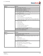
5.11.1 — Fuel Oil Circulating Pump
Failure or the circulating pump to deliver sufficient oil may be due to one of the following conditions:
1.
Insufficient fuel oil in the storage tank.
2.
Suction line or check valve clogged.
3.
Air leaks or air traps in the suction line. If the line has a high point at which an air trap can occur, the line
must be changed.
4.
Oil strainer clogged (line strainer or burner strainer).
5.
Suction line piping too small.
6.
Pump rotating in wrong direction.
7.
Three-phase pump motor operating on single phase because of fuse failure.
8.
Low voltage applied to pump motor.
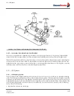
5.11.2 — Air-Oil Metering Pump
Both the integral air-oil metering pump for light oil and the heavy oil metering pump are precisely fitted nits
employing a seal on the shaft to prevent oil leakage. Internal wear can take place due to dirt in the oil and may
in time result in excessive clearances, reducing pump capacity. Once adjusted, the pump will continue to operate
with a minimum of readjustment. If burner failure appears to be caused by the metering pump, check the follow-
ing:
1.
See that the oil is at a sufficient level in both the fuel oil tank and the air-oil tank on the burner.
2.
Make sure all valves between the fuel oil tank and the burner are open.
3.
Be sure the oil suction line is not airbound and check the suction line strainer.
4.
Check the low fire setting of the metering pump to be sure it has not been disturbed.
5.
Make sure the pump turns freely.
6.
Inspect the burner oil nozzle for clogging.
Whenever an oil metering pump fails to deliver full capacity or pressure, order a replacement pump at once and
return the old pump for repair or exchange (where allowed).
NOTE:
Heavy fuel oil sometimes will not leak out through a suction line joint when the burner is idle, but the same
joint may allow air leakage inward when a vacuum is created in the line by pump action. The cause of a pulsating
burner fire can often be traced directly to air leakage in the oil suction line. Always be sure suction line joints are
absolutely air tight.
The metering pump is lubricated by fuel oil and must not be operated longer than one minute if it is not pumping oil.
Failure to comply will result in premature pump failure and void any warranty implied or otherwise.
Do not attempt to disassemble the oil metering pump in the field. Any attempt will void the warranty or the exchange
policy.
!
Caution
!
Caution
Summary of Contents for ProFire D Series
Page 2: ......
Page 8: ......
Page 16: ...viii 750 204 Profire D LND...
Page 30: ...Installation 2 2 750 204 Profire D LND FIGURE 2 1 Recommended Scotch Marine Chamber Dimensions...
Page 39: ...750 204 Profire D LND 2 11 2 13 Installation Checklist FIGURE 2 7 Recommended Pipe Size...
Page 40: ...Installation 2 12 750 204 Profire D LND FIGURE 2 8 Recommended Pipe Size...
Page 42: ...Installation 2 14 750 204 Profire D LND FIGURE 2 10 Recommended Pipe Size...
Page 43: ...750 204 Profire D LND 2 15 2 13 Installation Checklist FIGURE 2 11 Recommended Pipe Size...
Page 44: ...Installation 2 16 750 204 Profire D LND FIGURE 2 12 Recommended Pipe Size...
Page 45: ...750 204 Profire D LND 2 17 2 13 Installation Checklist FIGURE 2 13 Recommended Pipe Size...
Page 46: ...Installation 2 18 750 204 Profire D LND FIGURE 2 14 Recommended Pipe Size...
Page 50: ...Installation 2 22 750 204 Profire D LND...
Page 69: ...750 204 Profire D LND 4 11 4 8 Firing Rate Controls FIGURE 4 7 Motor Rotations...
Page 70: ...Adjustments 4 12 750 204 Profire D LND...
Page 82: ...Maintenance 5 12 750 204 Profire D LND...
Page 88: ...Troubleshooting 6 6 750 204 Profire D LND...
Page 98: ...Flue Gas Recirculation 8 6 750 204 Profire D LND FIGURE 8 4 FGR Piping and Valve Sizes...
Page 100: ...Flue Gas Recirculation 8 8 750 204 Profire D LND FIGURE 8 6 20 PPM Head Assembly...
Page 106: ...Parts Lists and Drawings 9 6 750 204 Profire D LND 9 4 2 Blast Tube Assembly D378 420...
Page 108: ...Parts Lists and Drawings 9 8 750 204 Profire D LND 9 4 3 Blower Housing Assembly D42 175...
Page 110: ...Parts Lists and Drawings 9 10 750 204 Profire D LND 9 4 4 Blower Housing Assembly D210 336...
Page 112: ...Parts Lists and Drawings 9 12 750 204 Profire D LND 9 4 5 Blower Housing Assembly D378 420...
Page 114: ...Parts Lists and Drawings 9 14 750 204 Profire D LND 9 4 6 Compressor Set D42 145...
Page 116: ...Parts Lists and Drawings 9 16 750 204 Profire D LND 9 4 7 Compressor Set D175 336...
Page 118: ...Parts Lists and Drawings 9 18 750 204 Profire D LND 9 4 8 Compressor Set D378 420...
Page 120: ...Parts Lists and Drawings 9 20 750 204 Profire D LND 9 4 9 Control Package Fireye...
Page 122: ...Parts Lists and Drawings 9 22 750 204 Profire D LND 9 4 10 Control Package Honeywell...
Page 124: ...Parts Lists and Drawings 9 24 750 204 Profire D LND 9 4 11 Damper Assembly D42 420...
Page 126: ...Parts Lists and Drawings 9 26 750 204 Profire D LND 9 4 12 Damper Assembly LND42 420...
Page 128: ...Parts Lists and Drawings 9 28 750 204 Profire D LND 9 4 13 Drawer Assembly D42 63...
Page 130: ...Parts Lists and Drawings 9 30 750 204 Profire D LND 9 4 14 Drawer Assembly D84 145...
Page 132: ...Parts Lists and Drawings 9 32 750 204 Profire D LND 9 4 15 Drawer Assembly D175 336...
Page 134: ...Parts Lists and Drawings 9 34 750 204 Profire D LND 9 4 16 Drawer Assembly D378 420...
Page 136: ...Parts Lists and Drawings 9 36 750 204 Profire D LND 9 4 17 Firing Head Assembly D42 420...
Page 139: ...750 204 Profire D LND 9 39 9 4 Parts Lists and Drawings 9 4 19 Oil Heater D42 420...
Page 146: ...Parts Lists and Drawings 9 46 750 204 Profire D LND 9 4 22 Oil Metering Assembly D378 420...
Page 156: ...750 204 Profire D LND...
Page 159: ......
Page 160: ......

