5
SERVICE INSTRUCTIONS
DISASSEMBLY
The tool should be clamped in the vise with the gear train in
a vertical position. Using a suitable wrench, unscrew the
gear case and slip the motor out of the motor housing.
NOTE: On the double reduction tools, the first reduction
spider will remain with the motor and should be removed at
this time. This completes the disassembly of the tool into
three (3) major subassemblies (Gear Case, Motor, and
Motor Housing). See the following paragraphs for complete
disassembly instruction.
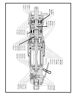
GEAR CASE: Holding the second gear case No. 613361, in
the vise, unscrew bearing retainer No. 203672. Drive third
reduction gear spider No. 204623, out of bearing No. 843615.
Unscrew second gear case No. 613361, from gear case.
The second reduction spider assembly may be pressed out
the rear of the gear case, No. 203691, after the retainer ring,
No. 864240, is removed from the inside of the gear case.
After the spider bearings have been removed, using a
suitable bearing puller, the idler gears may be removed for
inspection by driving the idler gear pins out the rear of the
spiders.
MOTOR: Using a soft-faced mallet, drive the rotor out of the
front rotor bearing, No. 619991. This will allow the removal
of the front bearing plate, No. 865344, cylinder, No. 864236,
and rotor blades, No. 869575. After removing the rotor lock
nut, No. 865352, from the rear rotor shaft, the rotor may be
driven out of the rear rotor bearing, No. 843444.
MOTOR HOUSING: The throttle valve, No. 869350, used in
the pistol grip handle may be removed for inspection by
unscrewing the inlet bushing, No. 833471. The lever back-
head throttle valve seal, No. 847366, may be removed by
unscrewing the throttle valve cap, No. 864531.
Unscrew the inlet bushing, No. 881276, for inspection and
cleaning of the air screen on the lever backhead.
REASSEMBLY
The tool is reassembled in the reverse of disassembly. All
parts should be thoroughly cleaned and inspected for wear
before reassembly. Replace all bearings which feel rough or
have excessive end play. The seals on bearing No. 619991
and No. 843615 should be checked closely and the bearing
should be replaced if visible damage is evident to the seals.
All other gears and open bearings should receive a gener-
ous amount of Shell #65115 Maleus compound during
assembly. After completing assembly of the gear case, and
prior to assembling it with the motor and motor housing,
additional Shell lubricant must be added until the gear case
cavity is approximately 2/3 full. Do not overfill.
To assemble the motor, install the rear rotor bearing into the
rear bearing plate. Make sure the outer bearing race is firmly
seated in the bearing plate. Clamp the rotor body lightly in the
vise with the threaded end up and slip the rear bearing plate
assembly onto the rotor shaft far enough for the rotor lock nut
to start. Tighten the lock nut until there is approximately
.0015" (.038mm) clearance between the rotor and bearing
plate. The outer bearing race should be firmly seated and the
rotor bumped forward when checking this clearance.
It is recommended that new rotor blades be installed at each
repair cycle. If not replaced, the used ones must measure a
minimum of 7/32" (5.5mm) at both ends.
The front motor bearing is sealed, so it cannot be packed
with greased. The rear rotor bearing should be packed with
a good grade of NLGI 2-EP grease after assembly of the
motor unit.
During assembly of the gear case to the motor and motor
housing, be sure that the teeth of the rotor mesh with the
teeth of the idler gears. Rotate the gear train by hand to be
sure the teeth are properly meshed before air is applied.
FOR YOUR SAFETY AND THE SAFETY OF OTHERS READ AND UNDERSTAND THE SAFETY
RECOMMENDATIONS BEFORE SERVICING TOOL.
SOFT
JAWED
VISE
.0015"
Clearance
Must be replaced if
7/32" (5.5mm) or less
at either end.


