background image

P1993BA-EN_2014-06_35PHHIVZ.fm, 12.06.2014

P1993BA/EN 2014-06

5

Contents

1

Safety

 7

1.1

Warnings and notes.....................................................................................................  7

1.2

Basic requirements for safe working practices ............................................................  7

1.3

Operator training .........................................................................................................  8

1.4

Personal protective equipment....................................................................................  8

1.5

Designated use ...........................................................................................................  8

1.6

Noise and vibrations....................................................................................................  8

2

Items supplied

 9

3

Product description

 9

3.1

Operation and functional elements..............................................................................  9

3.2

Options ......................................................................................................................   10

4

Before initial operation

 10

4.1

Air supply...................................................................................................................   10

4.2

Change air inlet: top / bottom (only on 35PHHA) ......................................................  11

4.3

Connect the tool ........................................................................................................  11

4.4

Setting up the tool .....................................................................................................  12

4.5

Troubleshooting.........................................................................................................  13

5

Maintenance

 15

5.1

Service schedule .......................................................................................................  15

5.2

Fill reserve oil ............................................................................................................  16

5.3

Complete oil filling .....................................................................................................  18

6

Disassembly instructions

 21

6.1

Remove motor unit ....................................................................................................  21

6.2

Remove throttle valve................................................................................................  22

6.3

Remove pulse unit.....................................................................................................  22

7

Assembly instructions

 23

7.1

Install motor unit ........................................................................................................  23

7.2

Install pulse unit.........................................................................................................  25

8

Spare parts

 27

8.1

Pistol grip 35PHH… ..................................................................................................  28

8.2

Pistol grip 35PHHA… ................................................................................................  30

8.3

Motor unit ..................................................................................................................  32

8.4

Pulse unit...................................................................................................................   34

8.5

Equipment order list ..................................................................................................  36

9

Technical data

 37

9.1

Dimensions 35PHH… in mm.....................................................................................  37

9.2

Dimensions 35PHHA… in mm ..................................................................................  38

Summary of Contents for 35PHH Series

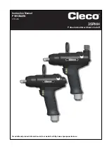
Page 1: ...For additional product information visit our website at http www apexpowertools eu 35PHH Pulse nutsetter without shutoff Instruction Manual P1993BA EN 2014 06...

Page 2: ...35PHH It serves as a reference work for technical data service intervals and spare part orders It points out options Secondary information P2204BA Instruction Manual Oil filling unit In the text 35PH...

Page 3: ...way shape or form in full or parts thereof or copied to another natural or machine readable language or to a data carrier whether electronic mechanical optical or otherwise without the express permiss...

Page 4: ...4 P1993BA EN 2014 06 1993a_ Deckblatt_en fm 12 06 2014...

Page 5: ...2 Change air inlet top bottom only on 35PHHA 11 4 3 Connect the tool 11 4 4 Setting up the tool 12 4 5 Troubleshooting 13 5 Maintenance 15 5 1 Service schedule 15 5 2 Fill reserve oil 16 5 3 Complete...

Page 6: ...6 P1993BA EN 2014 06 P1993BA EN_2014 06_35PHHIVZ fm 12 06 2014 9 3 Performance Data 39 9 4 Ambient conditions 39 10 Service 39 11 Disposal 39...

Page 7: ...the tool Before initial operation check that the suspension bail is properly fastened to the balancer 35PHHA Before using the air inlet from above make sure that the pipe plug is correctly fitted in...

Page 8: ...y Wear a hairnet Wear close fitting clothing Do not wear jewelry Sound level in the area of the user 80 dB A danger of hearing damage Wear hearing protection 1 5 Designated use The 35PHH is designed e...

Page 9: ...PHH 1 This instruction manual 1 Declaration of Conformity 1 Hex wrench WAF 2 3 Product description 3 1 Operation and functional elements Item Designation 1 Reverse switch 2 Exhaust air throttle torque...

Page 10: ...dry and clean Air preparation units Our recommendation air preparation units filters regulators lubricators should be installed Protective sleeve Order No 937448PT 35PHH Order No 937443PT 35PHHA Vibra...

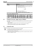
Page 11: ...screwing in torque 40 Nm Reaction torque at flat end Counterhold with wrench WAF 17 Activate compressed air 620 kPa Lubricator Compressed air requires a small amount of oil and is orientated to the ai...

Page 12: ...enings throttle the speed back at the tool until the required torque is achieved at the end of rotation of the fastening On hard to medium hard screwed joints this is achieved in 1 to 2 seconds Longer...

Page 13: ...ckwise To increase torque turn the exhaust air throttle counter clockwise NOTE The torque setting may be corrected when the compressed air is activated Error Possible causes Measures and remedies Tool...

Page 14: ...guide diameter Pressure fluctuations in the air network Use a pressure regulator Premature release of the start button Keep start button pressed until nut setter has stopped rotating Fastening time t...

Page 15: ...activation before service disconnect the tool from the compressed air supply Maintenance interval Rundowns Measures W1 100 000 Check the suspension bail for functional safety Check the air hose for we...

Page 16: ...ut the maintenance measures marked W2 after an operating time of 200 days 5 2 Fill reserve oil If X 0 see picture 2 the reserve oil is exhausted and must be refilled to guarantee a controlled process...

Page 17: ...nternal equalization hole is opened 4 To avoid air pockets fill the filling hole full of oil 5 Position the injector so that it has a sealing effect and add reserve oil until distance X for spacer B2...

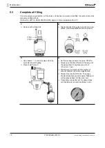
Page 18: ...cture internal equalization hole is opened 3 Use adapter to connect pulse unit to the quick disconnect coupling Close shutoff valve 4 Set the working pressure to approx 500 kPa Slowly open the shut of...

Page 19: ...the injector so that it has a sealing effect and add reserve oil until distance X for spacer B2 is achieved Maintain distance X and secure with B2 Refit set bolt and ball Remove B2 NOTE Small air bubb...

Page 20: ...20 P1993BA EN 2014 06 1994c_Wartung_en bedingt fm 12 06 2014 Maintenance 5 Empty side...

Page 21: ...1993BA EN 2014 06 21 Disassembly instructions 6 6 Disassembly instructions Please refer to 8 Spare parts page 27 and 8 5 Equipment order list page 36 6 1 Remove motor unit 1 2 Changing blades Changing...

Page 22: ...ring force 3 CAUTION Skin irritation in case of direct contact with oil Wear protective gloves CAUTION Hydraulic blade is under spring pressure Wear protective goggles NOTE Permitted only if filling i...

Page 23: ...motor unit CAUTION Only perform installation in accordance with exploded drawing see 8 3 Motor unit page 32 Incorrect installation can lead to uncontrolled reactions e g unexpected start up or parts b...

Page 24: ...ions 7 7 1 1 Install rotor cover 1 Press 59 in with C4 see X 2 Examine Y with thickness gage If dimension Y step 1 with support C5 C6 C7 repeat Press 61 in with C8 C8 59 C4 C5 C6 C7 X 54 55 X Base 0 0...

Page 25: ...ons 7 7 2 Install pulse unit 7 2 1 Assembling the hydraulic blades NOTE To prevent damage lubricate the gaskets and O rings using grease order no 914392 before assembly 1 2 3 4 5 6 7 8 F1 93 F1 98 93...

Page 26: ...26 P1993BA EN 2014 06 1994d_Reparatur_en bedingt fm 12 06 2014 Assembly instructions 7...

Page 27: ...nce and increased maintenance requirements If non original spare parts are installed the tool manufacturer is entitled to declare all warranty obligations for null and void We would be glad to prepare...

Page 28: ...28 P1993BA EN 2014 06 1993e_Ersatzteile_en fm 12 06 2014 Spare parts 8 8 1 Pistol grip 35PHH Adhesive order no 914860 Grease order no 914392...

Page 29: ...1993e_Ersatzteile_en fm 12 06 2014 P1993BA EN 2014 06 29 Spare parts 8 1 Order no 2 Quantity 3 Part of motor service kit K1 order no 936168 4 Dimensions...

Page 30: ...30 P1993BA EN 2014 06 1993e_Ersatzteile_en fm 12 06 2014 Spare parts 8 8 2 Pistol grip 35PHHA Adhesive order no 914860 Grease order no 914392...

Page 31: ...1993e_Ersatzteile_en fm 12 06 2014 P1993BA EN 2014 06 31 Spare parts 8 1 Order no 2 Quantity 3 Part of motor service kit K1 order no 936168 4 Dimensions...

Page 32: ...32 P1993BA EN 2014 06 1993e_Ersatzteile_en fm 12 06 2014 Spare parts 8 8 3 Motor unit Axial clearance see 7 1 1 Install rotor cover page 24...

Page 33: ...1 order no 936168 4 Dimensions Index 1 2 3 Description 4 29 936166 1 motor unit 53 936265 1 K1 ball 6 35 POM 54 936243 1 K1 ball bearing 12 X 24 X 6 55 936232 1 rotor cover 56 935458 1 rotor cylinder...

Page 34: ...1993e_Ersatzteile_en fm 12 06 2014 Spare parts 8 8 4 Pulse unit Tightening torque see 7 2 Install pulse unit page 25 For disassembly note the position of the balls in the control disc Reassemble balls...

Page 35: ...6 35 Spare parts 8 1 Order no 2 Quantity 3 Part of hydraulic service kit K2 order no 936211 4 Dimensions Order no 84 93 115 116 117 118 119 120 35PHH653 35PHHA653 936043 935410 35PHH65Q 35PHHA65Q 9360...

Page 36: ...36 P1993BA EN 2014 06 1993e_Ersatzteile_en fm 12 06 2014 Spare parts 8 8 5 Equipment order list 1 Order no...

Page 37: ...1993f_TechnDaten_en fm 12 06 2014 P1993BA EN 2014 06 37 Technical data 9 9 Technical data 9 1 Dimensions 35PHH in mm Abb 9 1...

Page 38: ...38 P1993BA EN 2014 06 1993f_TechnDaten_en fm 12 06 2014 Technical data 9 9 2 Dimensions 35PHHA in mm Abb 9 2...

Page 39: ...35PHHA65Q 1 4 1 04 1 10 Storage temperature 25 60 C Working temperature 5 40 C Permissible relative humidity 25 90 non condensing CAUTION Injuries and environmental damage from improper disposal The...

Page 40: ...0 Brazil Phone 55 15 3238 3820 Fax 55 15 3238 3938 Louisville Kentucky Apex Tool Group 1000 Glengarry Drive Suite 150 Fairdale KY 40118 Phone 1 502 708 3400 apexpowertools com service ASIA PACIFIC Ind...

Reviews: