background image

7

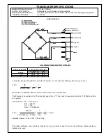
TRANSDUCER SPECIFICATIONS

MAXIMUM TORQUE CAPACITY

147 ft. lbs. (200 Nm)

OUTPUT VOLTAGE (Vo)

2 Millivolts per volt at maximum torque capacity

BRIDGE RESISTANCE (Rbr)

700 ohms (nominal) can be used with 350 and 700 ohm strain gage equipment*

TRANSDUCER CABLE

No. 203450

CALIBRATION INSTRUCTIONS

    ANGLE HEAD SIZE          FULL SCALE VALUE (FS)

               FT. LBS.              Nm

Straight

  147.5

             200

    "V"

  196.2

             266

    "X"

  312.7

             424

In order to calculate the calibration value for the system in % full scale, the following formula may be used:

% FS =              Rbr

      1

    1

     ------------------  X  -----  X  -----
     2(Rcal) + Rbr       Vo

    2

Where Rcal = Calibration Resistor Value in ohms of the torque monitor used.

The following is an example of a 75 series right angle tool, a "V" head and a torque monitor with a 110,000ohm calibra-
tion resistor.

The values are:    FS    = 196.2 ft. lbs.

Rbr   = 700ohm
Vo    = .002
Rcal  = 110,000ohm

                  700ohm

     1

    1

% FS =      ---------------------------  X   ------  X   -----     = 79.3%
             2(110,000ohm) + 700ohm    .002

    2

Calibration Value = 196.2 (.793) = 155.6 ft. lbs.

*Calculated calibration value should be doubled if a torque monitor designed for use with a 350ohm bridge resistance
transducer is used.

A

A

B

B

C

C

D

D

BLACK

GREEN

RED

WHITE

TOOL RECEPTACLE

CABLE CONNECTORS

R

WIRING DIAGRAM

E

E

F

F

(+) SIGNAL

(-) SIGNAL

SHIELD

(+) EXCITATION

(-) EXCITATION

Ro/2

Rm/2

R

R

R

t

C

t

C

Ro/2

Rm/2

Rcal

R= Gage Resistance
Rm= Modulus Resistor
Ro= Output Scaling Resistor
Rm & Ro may be omitted
Rcal= Shunt Calibration Resistor 

Summary of Contents for 75NLTVCE Series

Page 1: ...Vision Lights Positive VP Lever L Options Handle Transducer 75 Nutrunner 75 Series N T XX C E L X Gear Train Designation Output Drive Angle Terminations X X Built in Socket S Specify Size Threaded Sp...

Page 2: ...changing sockets Safety Recommendations make sure the air line is shut off and drained of air This will prevent the tool from operating if the throttle is acci dently engaged When using right angle n...

Page 3: ...ps and wrist supports are designed to reduce and moderate the effects of extended vibration exposure and repetitive wrist trauma Since they vary widely in design material thickness vibration reduction...

Page 4: ...ON PAGES 2 3 BEFORE OPERATING A NUTRUNNER TORQUE ADJUSTMENT The 75NLTVCE nutrunner is designed to develop maxi mum rated torque at 90 psig The torque setting is achieved by entering a number within th...

Page 5: ...the rear rotor bearing Motor Housing Clamptheflatsofthemotorhousingintheviseanduseastrap wrench to unscrew the handle No 202182 Disconnect the wirebundlefromthecableconnector No 202183 Remove solenoi...

Page 6: ...m torque range or tool will stall and not shut off REASSEMBLY GENERAL Thetoolisreassembledinthereverseorderofdisassembly Cleanallpartsthoroughlyinsolventandinspectfordamage or wear Check all bearings...

Page 7: ...hms of the torque monitor used The following is an example of a 75 series right angle tool a V head and a torque monitor with a 110 000ohm calibra tion resistor The values are FS 196 2 ft lbs Rbr 700o...

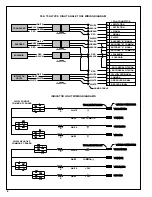
Page 8: ...WIRING DIAGRAM S S T T U U V V WHITE WHITE WHITE WHITE YELLOW LED YELLOW LED COMMON COMMON GREEN LED GREEN LED RED LED RED LED TOOL RECEPTACLE TOOL RECEPTACLE CABLE CONNECTORS CABLE CONNECTORS 24V COM...

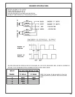
Page 9: ...LSIGNAL A BY90 ENCODER PULSES PER SPINDLE REVOLUTION BASED ON A 36 TOOTH ENCODER WHEEL EXAMPLE NUMBER OF PULSES TOTAL GEAR REDUCTION x NUMBER OF TEETH ON ENCODER WHEEL GEAR PULSES PER REVOLUTION TRAIN...

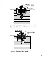
Page 10: ...015 020 as shown A new plunger pin should be spaced as shown however a previously used plunger pin must be pressed to this dimension 2 Assemble the solenoid components as shown Solenoid retainer must...

Page 11: ...JUSTMENT SCREW 5 64 HEX WRENCH SOLENOID SEAT VALVE PLUNGER SOLENOID RETAINER PLUNGER PIN HAT 4 Using a 5 64 hex wrench turn adjustment screw clockwise until plunger pin is pressed through hat and valv...

Page 12: ...V Bearing Cap Incl 867997 1 869877 Bearing Retainer 1 869878 Clamp Nut 1 869879 Clamp Ring 1 869880 Pinion Needle Bearing 1 869881 V Spindle Ball Bearing 1 869882 V Spindle Needle Bearing 1 869883 V...

Page 13: ...ler 13PerGear Idler Gear Pin NAME OF PART Transducer Encoder Assembly Roll Pin Sensor nut Transducer Shaft Transducer Ring Gear Transducer Housing Encoder Wheel Retainer Ring Drive Shaft Encoder Wheel...

Page 14: ...ing Plate RearBearingPlate RotorBlade PARTNO 865352 869923 869925 869927 QTY 1 1 1 1 2 NAMEOFPART Cylinder incl 812918 MotorSpacer Rotor CylinderPin RotorBearing 75NLTVCE NUTRUNNER MOTOR PARTS LIST MO...

Page 15: ...64530 1 865063 2 864195 3 812164 2 203053 4 617754 7 203549 1 203378 5 203379 3 203418 9 203550 9 203380 1 203377 7 863399 2 203553 3 869936 5 203263 9 203797 6 203798 4 203801 6 202183 0 202012 1 202...

Page 16: ...t SolenoidSeat Solenoid Retainer incl 863241 Air Inlet Valve Piston incl 866399 Shut off Valve incl 203379 ValveSeal Valve Cap incl 847710 ThrottleValveSpring Bushing Shut off Valve Cap incl 863454 Ba...

Page 17: ...ING RETAININGRING BALL BALLBEARING LOCK PIN RETAINER SOCKET LOCK PIN LOCK PIN SPRING PIPE PLUG RETAINER RING SET SCREW BEARINGRETAINER ROLLER BEARING QTY 1 1 1 1 1 1 1 1 1 1 1 1 22 1 1 1 1 1 1 1 1 1 P...

Page 18: ...18...

Page 19: ...19 NOTES...

Page 20: ...20 670 Industrial Drive Lexington SC 29072 Phone 803 359 1200 Fax 803 359 2013...

Reviews: