background image

81b_1_5 en bedingt.fm, 18.08.2008

P1880E/EN 2008-08

5

Safety

1

1

Safety

1.1

Warnings and notes

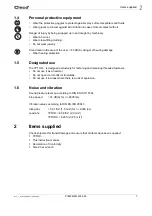
Warning notes are identified by a signal word and a pictogram:
• The signal word describes the severity and the probability of the impending danger.
• The pictogram describes the type of danger.

WARNING!

Indicates a potentially hazardous situation
which, if not avoided, could result in death or serious injury.

CAUTION!

Indicates a potentially hazardous situation which, if not avoided, may result in minor or moderate 
injury or property and environmental damage. If this warning is not observed, injuries, property 
or environmental damage may occur.

NOTE

General notes 

include application tips and particularly useful information but no hazard warnings.

Summary of Contents for 7PTHD Series

Page 1: ...Instruction Manual P1880E EN 2008 08 7PTHD Pulse shut off nutsetter...

Page 2: ...opied to another natural or machine readable language or to a data car rier whether electronic mechanical optical or otherwise without the express permission of Apex Tool Group In the text 7PTHD stand...

Page 3: ...peration 9 4 1 Ambient conditions 9 4 2 Air supply 9 4 3 Changing air inlet top buttom 7PTHDA only 9 4 4 Connect the tool 10 4 5 Setting up the tool 10 5 Troubleshooting 12 6 Maintenance 13 6 1 Servic...

Page 4: ...P1880E_EN 7PTHD 2008 08IVZ fm 18 08 2008 8 4 Pulse unit 32 8 5 Equipment order list 34 9 Technical data 35 9 1 Dimensions 7PTHD in mm 35 9 2 Dimensions 7PTHDA in mm 36 9 3 Performance Data 36 10 Servi...

Page 5: ...e type of danger WARNING Indicates a potentially hazardous situation which if not avoided could result in death or serious injury CAUTION Indicates a potentially hazardous situation which if not avoid...

Page 6: ...f you hear unusual noises or vibrations switch off the tool immediately Shut off the air supply immediately Before carrying out repairs adjusting the torque or replacing screw bits disconnect the tool...

Page 7: ...g protection 1 5 Designated use The 7PTHD is designed exclusively for fastening and releasing threaded fasteners Do not use it as a hammer Do not open it or modify it structurally Do not use it in are...

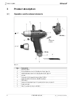
Page 8: ...1 Setting the torque page 10 3 Speed adjustment see 4 5 2 Changing the speed page 11 4 Air inlet 5 Connection for Pneumatic Torque Verifier TVP100 signal connection kit order no 934918 optional 6 Sta...

Page 9: ...rewed plug into air inlet at the top see demand Ambient temperature 41 F 5 C to a maximum of 104 F 40 C Permissible relative humidity 25 to 90 non condensing Parameter Data Air hose Inner diameter 3 8...

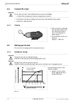
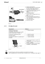
Page 10: ...in clockwise and counterclockwise rota tion at maximum speed see 4 5 2 Changing the speed page 11 Check the speed at the out put drive Target n 6000 rpm CAUTION Danger of injury from unintended startu...

Page 11: ...12 7 In case of deviations correct the torque setting 8 Repeat the rundown Requirement Measure Greater shut off accuracy particularly for hard joints Increase the number of pulses per rundown Recomme...

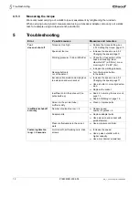
Page 12: ...5 m Increase the working pressure Reverse button is not at the detent Turn the reverse button to the detent Excessive transmission damping due to extension and worn socket Increase the speed see 4 5...

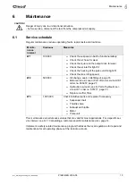
Page 13: ...unintentional activation before service disconnect the tool from the compressed air supply Mainte nance interval Rundowns Measures W1 100 000 Check the suspension bail for functional safety Check the...

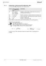
Page 14: ...conds soft joint and 3 completed shifts per day and 750 rundowns per shift You have to carry out the maintenance measures marked W2 after an operating time of 133 days Factor Value assumed in 6 1 Main...

Page 15: ...n reaches the limit stop oil must be refilled the next time see 6 3 Refilling oil page 16 1 2 Align both ends as shown in the illustra tion 3 4 Turn 68 clockwise till the detent 5 Turn back 68 counter...

Page 16: ...filling piece 1 3 Filling piece asm 1 4 Oil order no 925715 ESSO UNIVIS HVI26 approx 2 1 qt 2 liters temperature 68 9 F 20 5 C 5 Quick disconnect coupling 6 Working pressure 65 80 psi 450 550 kPa 7 Sh...

Page 17: ...of 13 psi 0 9 bar 90 kPa 10 Wait approx 2 minutes until the number of vacuum bubbles has reduced significantly 11 Close the shut off valve 7 slowly The gauge shows atmospheric pressure again Missing...

Page 18: ...18 P1880E EN 2008 08 81c_Wartung en bedingt fm 18 08 2008 Maintenance 6...

Page 19: ...instructions 7 7 Repair instructions Refer also to 8 Spare parts page 25 and 8 5 Equipment order list page 34 7 1 Disassembling the motor unit 7 2 Disassembling the throttle valve Changing blades Cha...

Page 20: ...ermitted only if filling is guaranteed with oil filling device see The pulse unit must have cooled to room temperature CAUTION Always carry out assembly according to the exploded drawing see 8 Spare p...

Page 21: ...ion Y 3 Press in 59 again if nec see dimension 4 Press 61 against 60 until flush 55 59 C4 C5 C6 C7 C8 54 59 54 X Dimension X 0 00 to 0 00236 0 00 to 0 06 mm Y Test force 1 12 3 37 lbf 5 15 N Y Dimensi...

Page 22: ...1880E EN 2008 08 81d_Reparatur en bedingt fm 18 08 2008 Repair instructions 7 7 4 2 Assembling the shut off piston 1 2 3 4 5 49 3 48 Don t use grease to hold the balls in place 44 45 47 Size 4 59 44 4...

Page 23: ...23 Repair instructions 7 7 4 3 Assembling the actuating ring 1 2 3 4 5 6 E 32 60 56 55 47 44 34 40 E 32 click 33 3 44 47 Dimension X 0 028 0 006 0 7 0 15 mm 34 34 Dimension X Inch 34 0 022 0 55 mm 93...

Page 24: ...7 5 Assembling the pulse unit 7 5 1 Assembling the hydraulic blades NOTE To prevent damage lubricate the gaskets and O rings using grease order no 914392 before assembly 1 2 3 4 5 6 7 8 73 F1 73 F1 7...

Page 25: ...decreased performance and an increased need for maintenance Installing replacement parts from other manufacturers will void all manufacturer s warranties We would be glad to prepare a special quote f...

Page 26: ...7 8 11 10 12 1 2 16 24 25 22 23 26 OFF 0 7 0 1 Nm 0 5 0 1 lbf ft 935490 SW2 OFF 20 2 Nm 14 8 1 5 lbf ft SW17 OFF 1 5 0 2 Nm 1 1 0 15 lbf ft 931030 SW2 5 OFF 0 7 0 1 Nm 0 5 0 1 lbf ft 1 ISO 4757 5 1 cl...

Page 27: ...en 8 905599 1 K1 circlip 11 X1 IR 9 S905998 1 K1 set bolt M 4X4 10 935673 1 reverse button 11 932160 1 countersunk screw M 3X 12 12 935442 1 suspension bail 13 935482 1 K1 compression spring 0 5 X 6 X...

Page 28: ...28 P1880E EN 2008 08 80e_Ersatzteile en fm 20 08 2008 Spare parts 8 8 2 Pistol grip 7PTHDA...

Page 29: ...7 905031 1 K1 screen 8 905599 1 K1 circlip 11 X1 IR 9 S905998 1 K1 set bolt M 4X4 10 935673 1 reverse button 11 932160 1 countersunk screw M 3X 12 12 935442 1 suspension bail 13 935482 1 K1 compressio...

Page 30: ...EN 2008 08 80e_Ersatzteile en fm 18 08 2008 Spare parts 8 8 3 Motor unit 935955 Axial clearance see 7 4 1 Assembling the end plate page 21 Reference dimension X see 7 4 3 Assembling the actuating rin...

Page 31: ...r 36 935451 1 K1 compression spring 40 935491 1 torque adjustment screw asm 41 902862 1 K1 circlip 10 X1 AR 44 935431 1 shut off piston 45 926570 1 K1 o ring 10 X1 47 935951 1 air distributor 48 91779...

Page 32: ...Ersatzteile en fm 18 08 2008 Spare parts 8 8 4 Pulse unit Tightening torque see 7 5 Assembling the pulse unit page 24 For disassembly note the position of the balls in the control disc Reassmble the b...

Page 33: ...ession spring 75 935676 1 control blade asm 76 935692 2 K2 compression spring 0 38X 2 7 X 33 77 935675 2 hydraulic blade 78 935678 1 control blade asm 79 935672 1 control disc 80 917793 8 K2 ball 2 50...

Page 34: ...933484 Support C2 933481 Semi monocoque pair C3 933480 Punch C4 933472 Support 0 mm C5 933473 Support 0 02 mm C6 933474 Support 0 04 mm C7 933475 Support 0 06 mm C8 933487 Punch C9 933476 Support 938...

Page 35: ...80f_TechnDaten en fm 18 08 2008 P1880E EN 2008 08 35 Technical data 9 9 Technical data 9 1 Dimensions 7PTHD in mm Abb 9 1...

Page 36: ...9 2 9 3 Performance Data Order no Recommended torque range Free speed 8 8 Air consumption ft lbf Nm ft3 min m3 min min max rpm mm lb kg Free speed Pulses 7PTHD602 7PTHDA602 1 4 2 9 4 5 2 7 6000 M5 1...

Page 37: ...roper disposal The components and auxiliary materials of a machine incorporate risks to health and the envi ronment Catch auxiliary materials oils greases when drained and dispose of them properly Sep...

Page 38: ......

Reviews: