Page 5
823108EN
12/31/2015
Cleco
®
Service
Chisel Removal:
Turn off the air supply and disconnect the air hose from
the tool before removing any chisel or implement.
Use only notched B1-C approved safety retainer chisels
with B1-C scalers and notched BR-C approved safety
retainer chisels with BR-C scalers. Refer to Illustration
“F” for a list of approved chisels.
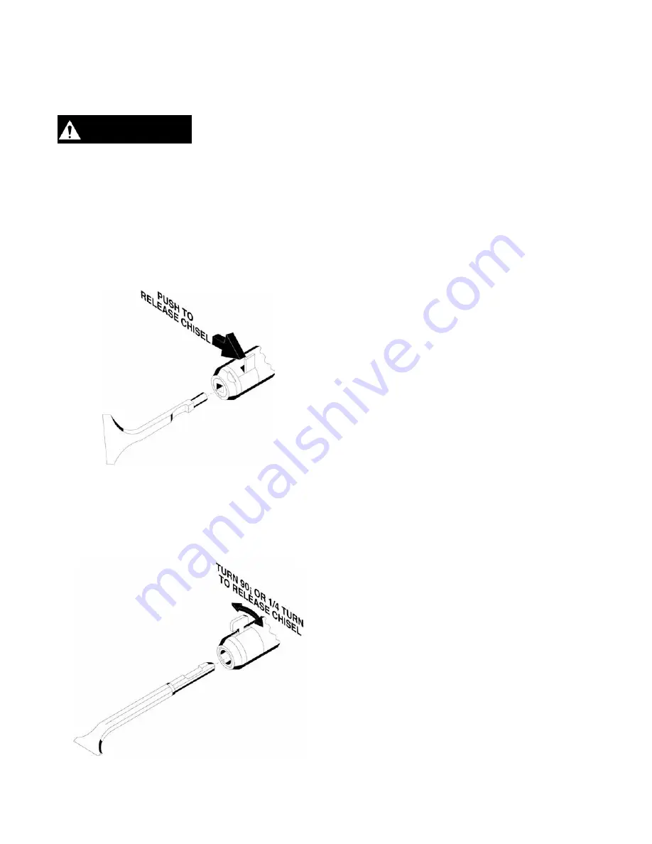
B1-C Series Models:
Push the tang on the driver retainer (832956), away from
the barrel to remove the chisel (see illustration below).
BR-C Series Models:
Rotate the driver retainer (869314) 90° or 1/4 turn in
either direction to remove the chisel (see illustration
below). Rotate the driver retainer back to its in-line
position with the barrel after chisel replacement.
Disassembly and Assembly:
Use Apex Tool Group, LLC or Apex Tool Group GmbH
& Co. OHG’s lightweight air tool oil 500021 (available
in quantities shown in the following chart) or an SAE-5
lightweight spindle oil.
B1-C-BV Pistol Grip Models:
Should if be necessary to replace the throttle valve
casing (832054), thread a 7/16-20 bolt into the casing
and using a suitable puller, remove it from the handle.
Refer to Illustration “C”.
Inspect Parts:
Clean and inspect all parts for excessive wear or
damage and replace as necessary with genuine Cleco
replacement parts. Replace all o-rings and seals
whenever the tool is disassembled.
Common issues to look for:
• Worn out retainer buffer (833527), used in the B1
series tools. This can be caused by operating the
tool without any resistance against the chisel.
• Excessive wear in the tool nose.
• Worn or scored plunger (832373 or 832944) usually
caused by foreign particles entering the tool.
• Worn or scored bore in the barrel sleeve (832700 or
832943) caused by foreign particles entering the tool.
Handle Assembly:
If the handle does not position as desired in relationship
to the chisel position, one or more handle positioning
shims (832947) may be placed between the valve
assembly and the handle. Refer to Illustrations “A”, “B”,
and “C”.
Use one shim for about every 30° desired. Always tighten
the handle into the barrel until the valve assembly is tight
against the barrel sleeve and then tighten the handle
lock ring (832882).
After the tool is assembled, pour a few drops of 10W
machine oil into the inlet bushing to ensure immediate
lubrication of the tool components.
B1-C-PT Series Throttle Valve Adjustment:
To adjust the throttle valve for the desired power, loosen
the throttle valve casing lock nut (843645) and screw the
controlling valve handle (832610) to a position so that
the desired blow is delivered when the handle is fully
compressed. Tighten the throttle valve casing lock nut to
secure the controlling valve handle in position. Refer to
Illustration “A”.
WARNING


