background image

Menus And Functions

Apex Tool Group

P2398PM  | 2022-07

17

3
EN

If the FastApp is blocked 

(under: 

), then the selection options are not available. In this case, 

a PIN must be entered to switch to another Linking group. A requirement is that a PIN has been defined in 
the PIN menu (

).

3.4.4

Selecting the Application/Linking group

To be able to switch between the Applications/Linking groups in mPro mode, the 

External Application  / LG 

Selection

must be activated on the controller.

1.

Select 

Navigator  > Advanced  > Tool Group > I/O

on the controller.

2.

Activate the checkbox 

External Application  / LG Selection

.

3.

In 

Mode

select the 

Tool Menu (Cordless Tool)

.

4.

To save the settings, press <Navigator>.

5.

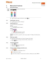
To change between the Applications/Linking groups on the tool, press 

or 

.

Only Applications/Linking groups that have already been parameterized can be selected.
A new display appears with the following selection options:

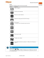
Button

Description

Press the 

button to select a new Application/Linking group.

must be pressed to cancel the process and return to the run screen.

The Application/Linking group can also be changed when the tool or control is offline. However, the run-
down cannot be done until the connection between tool and control has been re-established.

3.4.5

Counterclockwise rotation

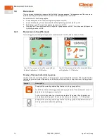
In the 

Counterclockwise  Rotation

menu, the tool rotates in the opposite direction of rotation as pro-

grammed for the FastApp in the controller or in the FastApps menu. During tightening, the display flashes 
yellow-gray. 

The speed for the counterclockwise rotation starts at 20 rpm and increases to 300 rpm.

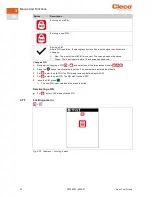
Fig. 3-5: Display during  counterclockwise rotation

To return to the run screen, press  .

Summary of Contents for CellCore S169262 CCBA

Page 1: ...For additional product information visit our website at www ClecoTools com Programming Manual P2398PM EN 2022 07 S169262 CCBA CCBP...

Page 2: ...echanical optical or other media without the express permission of the Apex Tool Group Disclaimer Apex Tool Group reserves the right to modify supplement or improve this document or the product with o...

Page 3: ...Application Linking group 17 3 4 5 Counterclockwise rotation 17 3 5 Main menu 18 3 6 FastApps menu 19 3 6 1 Configuring FastApps 20 3 6 2 Selecting the directionof rotation 22 3 6 3 Selecting the tig...

Page 4: ...5 3 11 Utility 46 3 11 1 Displaying thesoftware version 47 3 11 2 LiveWire API license 48 3 11 3 Saving an archive 49 3 11 4 Saving a torque graph 51 3 11 5 Loading parameters 54 3 11 6 Saving paramet...

Page 5: ...AP P2372JH Installation Instruction S168688 LiveWire Utilities P2390BA Instruction Manual CCBA CTBP P2402KA Quick Installation Guide CCBA CTBP Data Transmission P2403HW Hardware Description mPro200GC...

Page 6: ...could result in death or serious injury Caution A symbol combined with the word Caution indicates a hazard with a low level of risk which if not avoided could result in minoror moderate injury Note A...

Page 7: ...the controller and sent to the tool Fig 2 1 Display and tool controls Item Description 1 Micro USB B connection 2 Display 3 Confirmation button 4 Navigation buttons 2 1 Confirmation button Button Fun...

Page 8: ...alue jump by one Press to move the selection box to the left Press and hold to go to the run screen in the main menu Press and hold to jump up one menu level Press and hold to exit settings Press to d...

Page 9: ...seconds the tool switches off Option 3 The tool will switch off if it is not used for a certain time see chapter 3 7 4 Setting the shut off properties page 28 3 1 3 Selecting a button When talking ab...

Page 10: ...onfirm the follow ing messages 7 Parameterize the input signals Motor Start SS Remote Tool Start and Remote Tool Reverse Motor Start SS starts the motor of the tool and must always be set to forward t...

Page 11: ...nu and with warnings PIN is required The number on the lock indicates the active access level mPro mode is activated FastApps mode is activated Undervoltage limit is reached see chapter 3 7 4 Setting...

Page 12: ...ps mode This button is displayed on the run screen and in counterclockwise rotation must be pressed to go to the main menu Arrow down indicates that there are other menu items available that are not y...

Page 13: ...Menus And Functions Apex Tool Group P2398PM 2022 07 13 3 EN 3 3 Menu structure overview...

Page 14: ...n the controller Fig 3 2 Run screen in the mPro mode without External Application LG Selection Fig 3 3 Run screen in the mPro mode with Exter nal Application LG Selection Display of the Application Li...

Page 15: ...arrow pointing down appears next to the symbol the result is too low Display of the angle for the current tightening If an arrow pointing up appears next to the symbol the result is too high If an arr...

Page 16: ...ning positions 3 Display of the torque for the current tightening If an arrow pointing up appears next to the symbol the result is too high If an arrow pointing down appears next to the symbol the res...

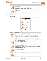
Page 17: ...n the tool press or Only Applications Linking groupsthat have already been parameterized can be selected A new display appears with the following selection options Button Description Press the button...

Page 18: ...Menus And Functions 18 P2398PM 2022 07 Apex Tool Group 3 EN 3 5 Main menu Fig 3 6 Main menu Button Description FastApps menu Settings Diagnostics WLAN communications Bluetooth communication Utility...

Page 19: ...urrent settings will not be carried over to the new mode Display of the currently selected FastApp Up to ten FastApps can be programmed The number on the button indicates which FastApp is selected Fas...

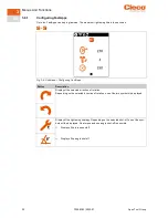
Page 20: ...Configuring FastApps Button Description Display of the selected direction of rotation Depending on the selected direction of rotation one of the two symbols is displayed Display of the tightening stra...

Page 21: ...al Speed 50 50 Speed Threshold 1 4 x of the Shut off Torque Threshold Torque These values can be changed manually in the menu see chapter 3 6 4 Ad vanced Settings page 23 Entering the Threshold Torque...

Page 22: ...tApps 3 6 2 Selecting the direction of rotation Fig 3 9 Submenu Selecting the direction of rotation Button Description Direction of rotation right hand thread Direction of rotation left hand thread 3...

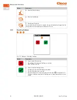
Page 23: ...orque shutoff enter the Shut off Torque For an angle shutoff enter the Shut off Angle Once the value has been reached the tightening processis ended Thissetting option is the same as in the menu see c...

Page 24: ...ximum Torque 3 6 5 Resetting FastApp Fig 3 12 Submenu Resetting FastApps Button Description Press to cancel the process The settings for the selected FastApp are not reset Reset FastApp is exited Pres...

Page 25: ...8PM 2022 07 25 3 EN 3 7 Settings Fig 3 13 Menu Settings Button Description Display and set time and date Adjust screen brightness Adjust tool light Set shut off properties Select torque units PIN menu...

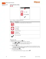
Page 26: ...ss the button 2 Enter the hour and minutes or the day month and year separately Use the and buttons to increase decrease the numbers Use the and buttons to switch between the input boxes 3 Confirm wit...

Page 27: ...dark and dimly lit Brightness Level 2 The LCD has medium illumination Thisis the default setting that is used when none of the buttons are selected outlined in green Brightness Level 3 The LCD is brig...

Page 28: ...is pressed Tool light is on during the tighten ing process untilthe Start switch is released 3 7 4 Setting the shut off properties This menu is only available in the FastApps mode In the mPro mode th...

Page 29: ...3 7 5 Selecting the torque units The torque values on the run screen are displayed in the selected units The selection is also used for the data export Fig 3 18 Submenu Selecting units Button Descript...

Page 30: ...PIN menu Button Description Access Level 1 Valid for the menu Access Level 2 Valid for the menu Access Level 3 Valid for the menu If only one PIN is defined then it applies to all the access levels PI...

Page 31: ...nu To open these menus a PIN must be entered Enter a PIN a PIN consists of four numbers 1 Enter four numbers The number on the lock indicates which PIN must be entered Use the and buttons to increase...

Page 32: ...ut is permissible The change can be saved Change a PIN 1 Navigate to Changing a PIN and select one of the three access levels 2 Press the button to activate the input box The numbers are entered indiv...

Page 33: ...on Lock activated Requirement A PIN must be activated To switch to another Linking group FastApp from the run screen a PIN must be en tered The functionality of the Start switch is not restricted Lock...

Page 34: ...Counters status Tool constant 3 8 1 Speed test This test function enables an evaluation of the speed The speed measurement is based on the angle information from the motor If the start button is relea...

Page 35: ...the Actual Angle If the test run is not aborted by a monitoring criterion and the total result is greater than or equal to 360 then it is evaluated as OK and displayed Monitoring criteria are the tor...

Page 36: ...isplay of the angle The displayed angle should be close to 360 3 8 3 Torque test With the torque test the functionality of the measuring sensor can be checked and the torque measure ment can be evalua...

Page 37: ...e Display of the maximum torque 3 8 4 Calibration value This test function allows an evaluation of the calibration voltage Fig 3 28 Submenu Calibration value Symbol Description Display of the neutral...

Page 38: ...voltage For high operational capability this voltage is continuouslymonitored during the tight ening process If the voltage drops below the undervoltage a warning is issued on the tool see chapter 3...

Page 39: ...menu is hidden Fig 3 31 Submenu Torque calibration value Button Description Display of the torque calibration value The tool constant can be changed by 20 To prevent unintentional changes to the tool...

Page 40: ...so that WLAN settings are assigned via DHCP this will appear to the right near the symbol as long as no connection could be established Fig 3 32 Menu Communications Button Description WLAN connection...

Page 41: ...deactivated Fig 3 33 Submenu Activating deactivating WLAN connection Button Description Press to cancel the process The WLAN connection is not activated deactivated The Activating deactivating WLAN c...

Page 42: ...assword of the WLAN infrastructure If not re quired enter any username and password The entry has no effect on the WLAN settings The WLAN settings cannot be transferred to the tool if these input fiel...

Page 43: ...he name of the controller is displayed with which the tool is connected via Bluetooth Select the node number The IP address ranges from 192 168 245 101 to 192 168 245 107 and depends on the node numbe...

Page 44: ...ated deactivated The Activating deactivating Bluetooth menu is exited Press to activate deactivate the Bluetooth connection The Bluetooth connection is activated deactivated The Activating deactivatin...

Page 45: ...roller and confirm with the but ton see document P2402KA for details Yellow background Connection establishment is ongoing Green background Bluetooth connection has been established Red background Blu...

Page 46: ...22 07 Apex Tool Group 3 EN 3 11 Utility Fig 3 38 Menu Utility Button Description Display of the software versions Save archive Save torque graph Load parameters Save parameters Software update Delete...

Page 47: ...witch off tool 3 11 1 Displaying the software version Fig 3 39 Submenu Displaying the software version Symbol Description Display of the software version for the measuring board Display of the softwar...

Page 48: ...20 White 31 12 9999 This date is displayed if there is no expiration date Yellow Date The expiration date has passed and the license is no longer valid Installing LiveWire API license The LiveWire API...

Page 49: ...bar is red or green Green The saving process has been successfully completed There is an OK in the status line Red An error occurred during the saving process see chapter Error messages software upda...

Page 50: ...orque Angle Angle AngleMin Minimum angle AngleMax Maximum angle Evaluation Evaluation of the result Either OK or NOK is entered Stage Fastening stage Reason Shut off cause see chapter 5 1 Error messag...

Page 51: ...d torque graphs After saving the status bar is red or green Green The saving process has been successfully completed There is an OK in the status line Red An error occurred during the saving process s...

Page 52: ...to the GraphicID for the ar chive Size Number of graphic points Torque low Nm Minimum Torque Torque high Nm Maximum Torque Torque Nm Shut Off Torque Angle low deg Minimum Angle Angle high deg Maximum...

Page 53: ...Date of export Day Month Year Time Time of export Hour Minute Second App Number of the FastApp ID Number of the graphic entry The number is identical to the GraphicID for the ar chive Tq low Nm Minim...

Page 54: ...separator Button Description For torque the decimal place is separated with a point For torque the decimal place is separated with a comma 3 11 5 Loading parameters All data except the archive data ar...

Page 55: ...with the extension zip 2 Connect the USB stick with the tool via the Micro B USB cable 3 Select 4 must be pressed to start the loading process The progressbar and status bar indicate when the data ar...

Page 56: ...the status bar is red or green Green The software update was successfully completed There is an OK in the status line Red An error occurred during the software update see chapter 5 Troubleshooting pag...

Page 57: ...he process The tightening results and the torque graphs are not deleted The Reset archive menu is exited Press to delete the archive All tightening results and torque graphs are deleted The Reset arch...

Page 58: ...tions 58 P2398PM 2022 07 Apex Tool Group 3 EN Button Description Press to reset the tool to factory settings All the settings of the tool and the archive are deleted The Resetting to factory settings...

Page 59: ...ntrolled tightening sequence with angle and torque check Fig 4 2 Representation of angle shut off The following description applies to both tightening sequences For the speed select a second speed par...

Page 60: ...rpm Speed Threshold rpm 1 Speed when the maximum torque is reached Must be less than the start ing Speed sein FastApps Modus As soon as the speed threshold is reached the speed is reduced from the st...

Page 61: ...Residual clamping force too great FSMW Not enough rundown data GD Gradient too small GD Gradient too large GEB Encoder error torque angle IP Error output section excessive current IRED Current TQ red...

Page 62: ...TQ Torque too low TQ Torque too high WG1D Error in Angle Encoder 1 WIG Total angle too small WIG Total angle too large ZRF Gear defective Error messages software updates and data storage Error messag...

Page 63: ...Accept Tool Settings again 1 Navigator Tool Setup 2 Select the line with the tool 3 Select Tool Settings Accept Tool not recognized Software incorrect Check controller and measuring card soft ware Fa...

Page 64: ...rammed Unlock the barcode type used 5 3 WLAN data communication problems WLAN data communication problems between controller and access point Problem Possible cause Measure No communication be tween t...

Page 65: ...P address IP address cannot be pinged IP address already exists in the network In this case the tool will not establish a connection Check the physical connection RSSI val ues Check the assigned IPadd...

Page 66: ...nnection Restart the tool and try to establish the Bluetooth connection again Restart the controller and try to establish the Bluetooth connection again The node number is as signed twice Make sure th...

Page 67: ...e 42 EAP TLS certificate 41 Error message data storage 62 Shut off cause 61 software update 62 F Factory settings 57 FastApps configure 20 lock 33 menu 19 reset 24 select 16 FastApps mode 7 9 19 Final...

Page 68: ...on 9 T Threshold Torque 21 23 Tightening sequence 59 Tightening strategy 15 22 Time 26 Tool light 27 Torque maximum 23 minimum 23 unit 29 Torque calibration value 39 Torque graph 51 torque shutoff 20...

Page 69: ......

Page 70: ...1 64 43 17 17 GERMANY Apex Tool Group GmbH Industriestra e 1 73463 Westhausen Germany Phone 49 0 73 6381 0 Fax 49 0 73 63 81 222 HUNGARY Apex Tool Group Hung ria Kft Plat nfa u 2 9027 Gy rHungary Phon...

Reviews: