11
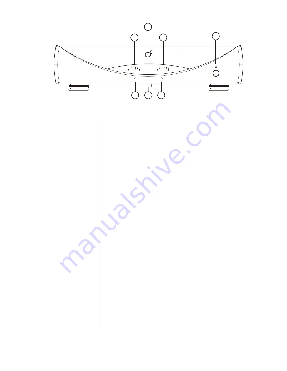
The numbers in the front panel illustration shown above correspond
with the numbered items that begin below.
1. Indicator LOGO
Indicates the operating state of the PureSINE-1000se.
1.1 Dimly lit Indicates that the PureSINE-1000se is in Standby.
1.2 Fully lit Indicates that the PureSINE-1000se is powered “on.”
2. On/Off Button
Places the PureSINE-1000se into standby mode and takes the
PureSINE-1000se out of standby mode. When the PureSINE-
1000se is powered on, pressing and releasing the On/Off button
places the PureSINE-1000se standby or takes thePureSINE-
1000se out of standby
3.
AC Input Display
Shows input voltage from AC mains.
4.
AC Pure SineWave Output Display
Shows Regulated AC line output from PureSINE-1000se
5.
Ground Indicator
Shows when AC input ground wire is connected properly.
6.
AC Phase Indicator
Shows when AC input Phase, Line and Neutral wires are connect
properly.
7.
Dimmer Switch
This button is located in the middle under the chassis. Press to
dim front panel LED display.
Front Panel
1
2
3
5
6
7
4
CLEF AUDIO
PureSINE-1000se
Ground
Phase


