ENGLISH
12
•
empty the recovery tank and the solution tank;
•
remove the squeegee and the brushes (or drive discs);
•
remove the batteries (in models with battery);
•
put the machine on the pallet, by anchoring it with plastic straps or the proper metal
brackets;
•
lift the pallet by means of a fork lift truck and load it on the vehicle;
•
anchor the machine to the vehicle with ropes connected to the pallet and to the
chassis of the machine.
6.
PRACTICAL GUIDE FOR THE USER
6.1
Control devices - Description
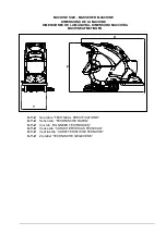
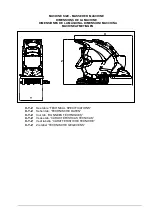
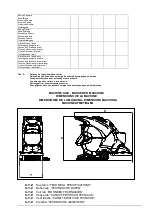
With reference to fig. 6 the machine has the following controls and leds:
•
Power supply led (fig. 6, ref. 1 – in models with cable only): it is green and indicates
that the power supply cable of the machine is connected to mains.
•
Battery charge check led (fig.6, ref. 1 – in models with battery only): consisting of 3
yellow leds, it indicates the battery charge level. It can be:
a) 3 leds on: batteries charged from 100% to 50%;
b) 2 leds on: batteries charged from 50% to 18%;
c) 1 led on: batteries almost flat;
d) 1 led blinking: batteries completely flat; after a few seconds the brushes are locked
and the brush switch light also comes on.
•
Main switch - emergency button with key (fig. 6, ref. 14): turns the power supply
to all machine functions on and off. It acts as a safety device. To start the machine
up, turn the key clockwise. To stop the machine, press the button.
•
Versions with mechanical drive: Brush switch with LED (fig. 6, ref. 3): enables
(“1”) or disables (“0”) the function “Brush”.
•
Versions with electric drive: Brush button with LED (fig. 6, ref. 3): enables (LED
on) or disables (LED off) the "Brush" function.
•
Versions with mechanical drive: Suction switch with LED (fig. 6, ref. 2): switches
on (“1”) or off (“0”) the suction motor, which allows to dry the floor just washed. The led
is on when the suction unit is fed.
•
Versions with electric drive: Suction button with LED (fig. 6, ref. 2): turns the
suction motor responsible for drying the floor on (LED on) or off (LED off). The light is
on when there is power to the suction motor.
•
Cock control lever (fig. 6, ref. 6): allows to adjust continuously the flow of solution
sent to the brushes. Pull up to increase the liquid outflow.
•
Drive control lever (fig. 6, ref. 7): the drive control lever permits forward movement of
the machine and rotation of the brushes.
•
Squeegee lifting lever (fig. 6, ref. 8): it allows to raise (when lifted) or lower (when
pushed down) the squeegee.
•
Direction adjustment knob (fig. 6, ref. 10): turn to correct any deviation of the
machine and keep it moving in a straight line.
•
Head lower/lift pedal (fig. 6, ref. 9): located on the left-hand side of the machine,
when pressed it lowers/raises the brush head.
•
Solution tank level indicator (fig. 6, ref. 5): the led comes on to indicate insufficient
water in the solution tank.
•
Recovery tank level indicator (fig. 6, ref. 4): when the recovery tank is full the led
comes on and after a few seconds the suction motor locks out.

