background image


ENGLISH 

16 

machine forward. The special mechanical drive device uses the friction between brush 
and floor to generate a thrust forward; when the mechanical drive lever is released, the 
brush motor will therefore switch off and the machine will consequently stop.  
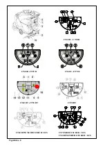
If necessary, correct any deviation of the machine and keep it moving in a straight line 
via  the  direction  adjustment  knob  (fig.  6,  ref.  10):  if  the  machine  tends  to  veer  to  the 
right, rotate the knob clockwise and vice versa. 

  Versions with electrical drive: to move forwards or backwards, see paragraph 6.3. 

In both versions: 

  periodically  check  that  the  detergent  solution  reaches  the  brushes  and  refill  when 

finished; when water in the solution tank is no longer sufficient, the level indicator will 
come on (fig. 6, ref. 5): stop and fill the tank; 

  during work check the cleaning quality and adjust the solution flow sent to the brushes 

by raising or lowering the lever (fig. 6, ref. 6) as required. 

 WARNING 

Whenever you fill up the solution tank, always empty the recovery tank. 

Do not leave the machine stationary with the suction motor on and the solution 

cock turned on. 

  If the recovery tank is full, the level indicator will come on (fig. 6, ref 4) and after a few 

seconds the suction motor will lock out: stop and empty the tank; to re-start the suction 
motor, switch the suction switch off and then on again (fig. 6, ref. 2). 

  Models with battery: if the warning led (fig. 6, ref. 1) starts flashing, it means that the 

storage  batteries  are  getting  flat.  After  a  few  seconds  the  brushes  lock  to  prevent 
excessive unload. Load them. 

At the end of work: 

  move the cock lever (fig. 6, ref. 6) to the position “CLOSED”; 

  release the brush/drive lever (fig. 6, ref. 7) placed beneath the handle: the brush/drive 

motor switches off and the machine stops; 

  press “0” on the brush switch (fig. 6, ref. 3) to disable the function “Brush”; 

  raising  the  lever  (fig.  6,  ref.  8),  lift  the  scrubber  from  the  floor  to  prevent  the  drying 

blades from warping due to the continuous pressure; 

  let the suction motor run for at least 2 minutes to make sure that it is completely dry; 

then press "0" on the suction unit switch (fig. 6, ref. 2) to switch off the suction motor; 

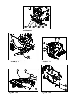
  remove the brushes (or drive discs) to prevent them from warping permanently; 

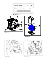
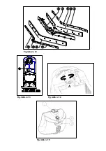
  depending  on  the  model,  unplug  the  machine  or  disconnect  the  ANDERSON 

connectors (fig. 5, ref. 1 and ref. 2); 

  empty and clean the recovery tank. 

 WARNING 

Both lead-acid batteries (set by default) and gel batteries can be installed. If gel 

batteries are installed, the dealer must operate the switch on the control panel 

electronic board. 

6.8 

Some useful suggestions for the optimal use of the machine 

If the floor presents a particularly resistant type of dirt, it is possible to make the machine 
wash and dry it in separate stages. 

6.8.1  Pre-washing 

  Open the water cock; 

  set the brush switch to position “1”; 

  lower the head; 

  operate the drive lever to rotate the brushes; 

  ensure that the suction device is off and that the squeegee is raised; 

Summary of Contents for CT90 60BT

Page 1: ...SCRUBBER DRYER OPERATOR MANUAL Clemas Co Unit 5 Ashchurch Business Centre Alexandra Way Tewkesbury Gloucestershire GL20 8NB Tel 01684 850777 Fax 01684 850707 Email info clemas co uk Web www clemas co...

Page 2: ...es max Presi n cepillo max Pressione spazzole max Max borsteldruk gr cm 31 5 23 58 21 79 Brush rotation speed Geschwindigkeit der B rstendrehung Vitesse de rotation de la brosse Velocidad rotaci n del...

Page 3: ...0 180 200 180 200 Single battery weight Gewicht der einzelnen Batterie Poids de chaque batterie Peso bater a individual Peso singola batteria Gewicht afzonderlijke batterij Kg 32 32 32 Power supply ca...

Page 4: ...ora Potenza Sonora Geluidsvermogen Vibration Level arm Schwingungspegel arm Niveau de Vibrations bras Nivel de Vibraciones brazo Livello Vibrazioni braccio Trillingsniveau arm Vibration Level hand arm...

Page 5: ...UINA DIMENSIONI MACCHINA MACHINEAFMETINGEN X Y Z See table TECHNICAL SPECIFICATIONS X Y Z Sehen tab TECHNISCHE DATEN X Y Z Voir tab DONNEES TECHNIQUES X Y Z Vease tab CARACTER STICAS T CNICAS X Y Z Ve...

Page 6: ...UINA DIMENSIONI MACCHINA MACHINEAFMETINGEN X Y Z See table TECHNICAL SPECIFICATIONS X Y Z Sehen tab TECHNISCHE DATEN X Y Z Voir tab DONNEES TECHNIQUES X Y Z Vease tab CARACTER STICAS T CNICAS X Y Z Ve...

Page 7: ...u hand arm Tab A Data can be changed without notice Deiese Daten k nnen ohne vorherige Benachrichtigung ge ndert werden Donn es techniques pouvant changer sans pr avis Los datos pueden variar sin avis...

Page 8: ...ENGLISH...

Page 9: ...TING AND HANDLING THE MACHINE 11 6 PRACTICAL GUIDE FOR THE USER 12 6 1 CONTROL DEVICES DESCRIPTION 12 6 2 INSTALLING AND ADJUSTING THE SQUEEGEE 13 6 3 MOVEMENT OF THE MACHINE WHEN NOT OPERATING 13 6 4...

Page 10: ...ENGLISH 3 10 HOW TO ORDER SPARE PARTS 21 11 TROUBLESHOOTING 22 11 1 HOW TO OVERCOME POSSIBLE FAILURES 22...

Page 11: ...d letters and preceded by symbols illustrated and defined below DANGER Indicates that attention must be paid to avoid serious consequences that could cause the death of the personnel or possible damag...

Page 12: ...ater and detergent and brushes it to remove dirt Choosing with care the right cleaning detergent and brushes or abrasive discs in the wide range of accessories available the machine can adapt itself t...

Page 13: ...propilene brushes used for normal floor washing Tynex brushes used to remove accumulated stubborn dirt on resistant floors Drive discs allow the use of the following discs yellow discs used for washin...

Page 14: ...le of causing serious accidents before starting to work remove trinkets watches neckties or other such things Always use individual safety protections apron or protective suit overalls non slip water...

Page 15: ...nufacturer is permitted as only these offer the certainty that the machine will operate safely and without any inconveniences Do not use parts removed from other machines or other kits as spares This...

Page 16: ...nvelope 2 1 battery bridge with clips for battery models only 1 pair of tweezers for fuses for battery models only 1 connector for the battery charger for battery models only depending on the model re...

Page 17: ...overalls etc to limit the hazards of accidents keep away from possible free flames do not short circuit the battery poles cause sparks or smoke The batteries are normally supplied filled with acid an...

Page 18: ...ring connector fig 5 ref 2 to the machine wiring connector fig 5 ref 1 9 use the machine in compliance with the instructions written below 5 6 The battery charger models with battery WARNING Never let...

Page 19: ...the button Versions with mechanical drive Brush switch with LED fig 6 ref 3 enables 1 or disables 0 the function Brush Versions with electric drive Brush button with LED fig 6 ref 3 enables LED on or...

Page 20: ...erating To move the machine perform the following operations 1 raise the squeegee 2 push the head movement pedal down and then to the right fig 6 ref 9 to raise the head 3 move as follows versions wit...

Page 21: ...e maximum temperatures indicated in the technical data and must be free from sand and or other impurities The machine has been designed to be used with non foaming and biodegradable detergents specifi...

Page 22: ...ank before refilling the solution tank For an effective cleaning and long life of the equipment it is necessary to follow some simple rules prepare the work area keeping away the possible obstacles be...

Page 23: ...ith battery if the warning led fig 6 ref 1 starts flashing it means that the storage batteries are getting flat After a few seconds the brushes lock to prevent excessive unload Load them At the end of...

Page 24: ...ng fig 8 ref 3 and pull it horizontally keeping the hose end as much high as possible take off the drain cock fig 8 ref 4 by unscrewing it lower the hose end gradually checking the intensity of the je...

Page 25: ...k the battery charge by producing sparks The batteries give off inflammable vapours put out any fire or embers before checking and filling up the batteries Perform the operations described below in ai...

Page 26: ...the filter has been replaced in its seat correctly screw again the cap on the recovery tank 9 2 2 Basket filter cleaning Take the basket filter out of the water inlet at the front of the machine clean...

Page 27: ...gue WARNING Never fit a fuse with a higher Amp value than the intended one If a fuse keeps burning it is necessary to identify and repair the damages present in the wiring boards if fitted or motors h...

Page 28: ...in your orders with the following data machine model machine serial number on the identification plate see fig 1 chart of the list of spare parts in which the item and its reference number are found...

Page 29: ...again the power supply connector or the motor thermal protection connector C the motor power supply connector is disconnected C connect again the motor power supply connector B BT the brush motor fus...

Page 30: ...ery tank or make the necessary repairs to the float there is an obstruction in the suction tube free the tube from the obstruction the suction tube is not connected to the squeegee or is damaged conne...

Page 31: ...hine is used at its maximum capacity for continuous periods and the autonomy is not sufficient use if possible storage batteries with larger capacity or replace the storage batteries with others alrea...

Page 32: ...ttery charger the battery charger does not work check that there is voltage at the battery charger that the fuses are not interrupted and that there is current at the storage battery in addition try t...

Page 33: ...T Motor thermal cutout tripped 6 LIM Board mosfet thermal limitation problem 7 BLT Drive block Appears when the battery voltage is too low and the drive is blocked 8 AcS Brush Control Fault Appears wh...

Page 34: ...Fig Abb 1 Fig Abb 2 Fig Abb 3 Fig Abb 4 Fig Abb 5...

Page 35: ...Fig Abb 6 CT40 CT70 C only CT40 R CT70 R CT40 B CT70 B CT40 C CT70 C CT40 BT CT70 BT CT90 BT CT40 BT50 MICRO SCRUB ECS CT70 MICRO SCRUB ECS CT40 BT60 MICRO SCRUB ECS...

Page 36: ...Fig Abb 7 Fig Abb 9 Fig Abb 8 Fig Abb 10 Fig Abb 11 1 3 2 4 5...

Page 37: ...Fig Abb 12 Fig Abb 13 Fig Abb 14 Fig Abb 15 A...

Page 38: ...Fig Abb 16 Fig Abb 17...

Page 39: ...Fig Abb 18 Fig Abb 19...

Reviews: