background image

OPERATION

EN

Tennant T2 (07--08)

9

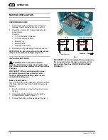
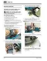
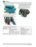
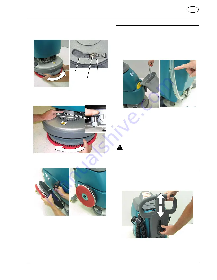
5. Align the pad driver/brush mounting studs with

motor hub slots and give the pad driver/brush a

quick counter--clockwise turn to engage spring clip

(Figure 11).

Spring Clip

Pad Driver/Brush

Mounting Stud

Motor Hub

Slot

FIG. 11

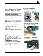
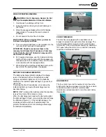
6. To remove the pad driver/ brush, press down on

the motor hub lock pin and turn the pad

driver/brush clockwise (Figure 12).

Lock Pin

FIG. 12

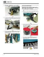
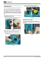
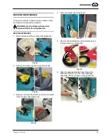
7. When transporting or storing machine, remove the

brush and hang it on the storage strap (Figure 13).

FIG. 13

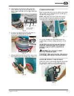
FILLING SOLUTION TANK

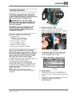
Remove the solution tank cover and fill the tank with 26

liters of water (<60

°

C temperature). Do not fill beyond

the “MAX” level (Figure 14).

NOTE:

When filling the solution tank with a bucket,

make sure that the bucket is clean. Do not use the

same bucket for filling and draining the machine.

FIG. 14

Pour a recommended cleaning detergent into the

solution tank according to mixing instructions on the

bottle.

ATTENTION: Only use recommended cleaning

detergents. Machine damage due to improper

detergent usage will void the manufacturer’s

warranty.

WARNING: Fire or Explosion Hazard.

Never Use Flammable Liquids.

FOR SAFETY: When using machine, follow mixing

and handling instructions on chemical containers.

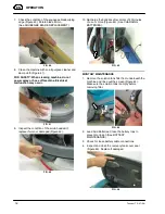
ADJUSTING CONTROL CONSOLE HEIGHT

Loosen the control console height adjustment knob and

lift or lower the console to a comfortable operating

height. Tighten knob to lock in position (Figure 15).

FIG. 15

Summary of Contents for TENNANT T2

Page 1: ...T T2 SCRUBBER DRYER OPERATOR MANUAL Clemas Co Unit 5 Ashchurch Business Centre Alexandra Way Tewkesbury Gloucestershire GL20 8NB Tel 01684 850777 Fax 01684 850707 Email info clemas co uk Web www clemas co uk ...

Page 2: ...FORMITY TENNANT Europe Uden Industrielaan 6 5405 AB P O Box 6 5400 AA Uden The Netherlands Uden 01 08 08 Machine Type T2 Scrubber Dryer No MT2 EN This machine is in conformity with the following directives and standards S Machinery Directive 98 37 EC S EMC Directive 89 336 EC 91 263 EC 92 31 EC 93 67 EC 93 68 EC S Harmonized Standards EN 292 1 292 2 292 3 1050 418 982 1037 60204 1 61310 1 61310 2 ...

Page 3: ...Machine FOR SAFETY 1 Do not operate machine In an area where flammable liquids vapors or combustible dusts are present Unless trained and authorized Unless operator manual is read and understood If not in proper operating condition 2 Before starting machine Make sure all safety devices are in place and operate properly Place wet floor signs as needed 3 When using machine Go slow on inclines and sl...

Page 4: ...Turn Off Power Before Working On Machine READ MANUAL LABEL Located on recovery tank cover FOR SAFETY Do not operate machine unless operation manual is read and understood BATTERY CHARGE LABEL Located at bottom side of recovery tank WARNING Fire Or Explosion Hazard Batteries Emit Hydrogen Gas Keep Sparks And Open Flame Away Keep Battery Compartment Open When Charging WARNING Fire or Explosion Hazar...

Page 5: ...Lift Pedal 11 Squeegee Vacuum Hose 12 Squeegee Assembly 13 Wall Roller 14 On board Battery Charger optional 15 Hour Meter 16 Solution Tank Fill Gauge Drain Hose 17 Squeegee Storage Bracket 18 Cup Holder 19 Recovery Tank Cover 20 Recovery Tank 21 Solution Tank Fill Port 22 Solution Tank 23 Pad Driver Brush Lock Release Button 24 Pad Driver Window 25 Scrub Head 26 Scrub Head Skirt 27 Solution Flow C...

Page 6: ...en Gas Keep Sparks And Open Flame Away Keep Battery Hood Open When Charging FOR SAFETY When servicing machine wear protective gloves and eye protection when handling batteries and battery cables Avoid contact with battery acid Battery Specifications Two 12 volt 70Ah 5h Gel 994200 72Ah 5h lead acid 1041458 85Ah 5h lead acid 1041454 deep cycle batteries 1 Park the machine on a level surface and remo...

Page 7: ...pregnated with abrasive grit to remove stains and soilage Strong action on any surface Performs well on buildup grease or tire marks Polishing Pad White Part No 994530 Used to maintain highly polished or burnished floors Buffing Pad Red Part No 994531 Used for light duty scrubbing without removing floor finish Scrubbing Pad Blue Part No 994532 Used for medium to heavy duty scrubbing Removes dirt s...

Page 8: ... the storage bracket Figure 7 FIG 7 INSTALLING BRUSHES PADS FOR SAFETY Before installing brushes or pad drivers stop machine on level surface remove key and set parking brake if equipped 1 Park the machine on a level surface and remove key 2 Step down on the scrub head lift pedal to raise the scrub head off the floor Figure 8 FIG 8 3 Attach the pad to the pad driver and secure pad with centerlock ...

Page 9: ...perature Do not fill beyond the MAX level Figure 14 NOTE When filling the solution tank with a bucket make sure that the bucket is clean Do not use the same bucket for filling and draining the machine FIG 14 Pour a recommended cleaning detergent into the solution tank according to mixing instructions on the bottle ATTENTION Only use recommended cleaning detergents Machine damage due to improper de...

Page 10: ...ub head skirt for wear OPERATING THE MACHINE 1 Turn the main power key switch to the on I position Figure 16 FIG 16 2 Lower the squeegee assembly to the floor by moving the squeegee lift lever to the left Figure 17 The vacuum motor will automatically turn on FIG 17 3 Lower the scrub head to the floor by stepping on the scrub head lift pedal as shown Figure 18 FIG 18 4 Pull the start triggers and s...

Page 11: ...evel of the batteries When the batteries are fully charged all indicator lights are lit As the batteries discharge the indicator lights will begin to go out from right to left To prolong the life of the batteries do not allow the indicator lights to go beyond the discharge level as described below NOTE ONLY recharge the batteries when the machine is used for a total of 30 minutes or more When the ...

Page 12: ...VERY TANK 1 While holding the drain hose upward remove the cap and lower hose to drain Figure 24 FIG 24 NOTE When using a bucket to drain the machine do not use the same bucket to fill the solution tank 2 Open the recovery tank cover and rinse out the tank Figure 25 FIG 25 3 Clean the float shut off screen and debris tray located in the recovery tank Figure 26 FIG 26 DRAINING SOLUTION TANK To drai...

Page 13: ... may result in battery damage To determine your battery type see battery label If not specified contact your battery supplier To verify the setting of the charger profile During charger start up if the red light flashes twice the charger is set for wet lead acid batteries If the green light flashes twice the charger is set for a Gel batteries Figure 28 NOTE Refer to the Charger Profile Switch Conf...

Page 14: ...cord If the charger detects a problem the charger will display an fault code See ON BOARD BATTERY CHARGER FAULT CODES FIG 33 ON BOARD BATTERY CHARGER FAULT CODES FAULT CODE FAULT SOLUTION Yellow Light Flashing Loose charger cable connection Check charger cable connection Loose or damaged battery cable Check battery cable connections Unsuitable battery Replace with proper battery Output short circu...

Page 15: ...rinse out the recovery tank Figure 34 FIG 34 2 Remove the debris tray and empty Figure 35 FIG 35 3 Remove and clean the float shut off screen located in the recovery tank Figure 36 FIG 36 4 Drain the solution tank Figure 37 FIG 37 5 Remove the pad brush and clean Rotate pad or replace when worn Figure 38 FIG 38 6 Wipe the squeegee blades clean Figure 39 When machine is not in use raise squeegee as...

Page 16: ...e scrub head skirt replace if worn or damaged Figure 42 FIG 42 10 Recharge the batteries after a total of 30 minutes of use or more Figure 43 See CHARGING BATTERIES FIG 43 MONTHLY MAINTENANCE 1 Remove the solution tank filter from underneath the machine and rinse out the screen Figure 44 Make sure the solution tank is empty before removing filter FIG 44 2 Lead Acid Batteries Clean the battery tops...

Page 17: ...ne 2 Loosen the band clamp and remove the band from the squeegee assembly Figure 46 FIG 46 3 Remove and rotate the rear blade to a new wiping edge Figure 47 FIG 47 4 Remove the thumb screws from the front blade and rotate blade end for end Figure 48 NOTE Use the 5 slot edge use on VCT flooring vinyl composite tile and the 3 slot edge on grouted tile floors FIG 48 BATTERY MAINTENANCE Lead Acid Batt...

Page 18: ...k or trailer STORING MACHINE 1 Charge the batteries before storing Never store the machine with discharged batteries 2 Drain and rinse the tanks thoroughly 3 Store the machine in a dry area with the squeegee and scrub head in the up position 4 Open the recovery tank cover to promote air circulation ATTENTION Do not expose machine to rain store indoors 5 If storing machine in freezing temperatures ...

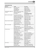
Page 19: ...s Contact Service Center Little or no solution flow Clogged solution tank filter or solution hose Clean solution tank filter or flush out solution hose Clogged solution valve Remove valve and clean Solution flow control knob set too low Adjust solution control flow knob Loose screw on control knob Calibrate knob and retighten screw Poor water pickup Recovery tank is full Drain recovery tank Loose ...

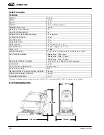
Page 20: ...FT 100 Mbar BATTERY CAPACITY 2 12 V 85 Ah 5 hr rate 72 Ah 5 hr rate 70 Ah 5 hr rate RUN TIME PER CHARGE 85Ah Batteries Up to 2 hours 72Ah Batteries Up to 1 75 hours 70Ah Batteries Up to 1 75 hours ON BOARD BATTERY CHARGER 100 240 VAC 5 3 A 50 60 Hz 24 VDC 9 A output VOLTAGE DC 24 VDC TOTAL POWER CONSUMPTION 25 Amp nominal PROTECTION GRADE IPX3 DECIBEL RATING AT OPERATOR S EAR INDOORS 68 dB A VIBRA...

Reviews: