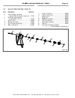
POWER GUN SUCTION BLAST TOOLS
Page 8
© 2018 CLEMCO INDUSTRIES CORP.
www.clemcoindustries.com
Manual No. 24189, Rev. C 06/18
5.3.2
Open the water valve only after the pulling the
trigger to begin blasting and closed before releasing the
trigger to stop blasting.
NOTICE
Open the water valve only after pulling the
trigger to begin blasting and always close it
before releasing the trigger to stop blasting.
Failure to have the water valve closed when the
trigger is released can allow water to flow into
the mixing chamber and material hose, causing
blockage from wet abrasive.
5.4
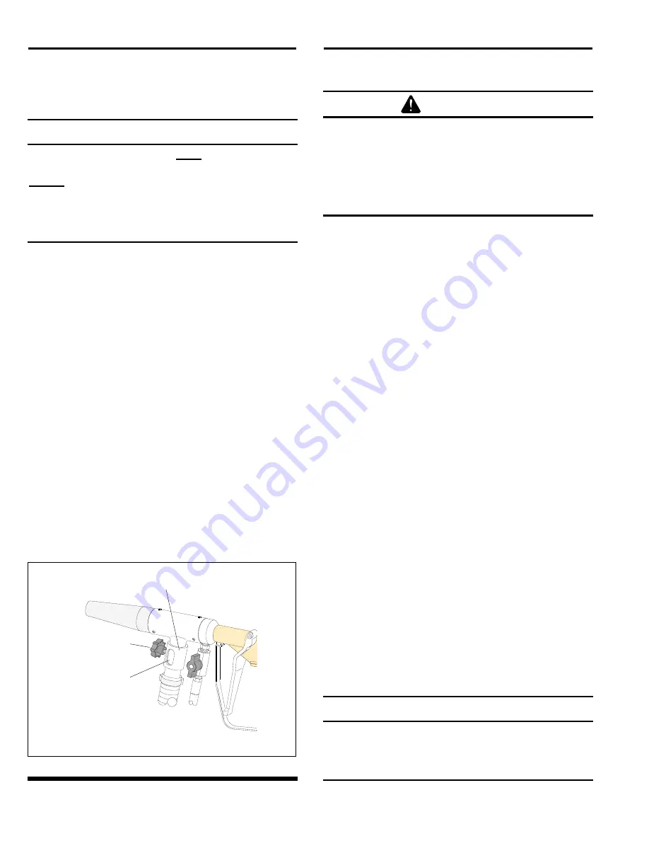
Air-Induction Valve (stops abrasive flow)
Figure 12
5.4.1
Opening the air-induction valve disrupts the
vacuum used to pull abrasive into the mixing chamber
allowing air only (no abrasive) to exit the nozzle. This step
is used to blow off dry abrasive from the blast surface or
assist in drying a wet surface after wet blasting.
5.4.2
To stop abrasive flow, loosen the tensioning
knob and rotate the sleeve to fully open the induction
port. Close the valve to resume blasting.
Wash Down:
If the water valve is open, air and water
continue to flow through the nozzle (as long as the
trigger is pulled) to wash off the blast surface. Refer to
Section 4.6.5.
Air Drying and Blow-Off:
If the water valve is closed,
air continues to flow through the nozzle (as long as the
trigger is pulled) to blow-off dry surface or assist in dry
wet surfaces. Refer to Section 4.6.6.
Figure
12
6.0 MAINTENANCE
WARNING
Failure to observe the following procedure
before performing any maintenance or service
can cause serious injury or death from the
sudden release of compressed air.
Lockout and tagout the compressed-air
supply.
Bleed the air-supply line.
Periodically inspect the air jet, mixing chamber, nozzle,
and material hose for wear.
6.1
Removing Nozzle and Air Jet:
There are no
threads on the mixing chamber; the jet and nozzle are
held onto the mixing chamber with three setscrews. Use
a 2.5 mm hex key to loosen the setscrews and while
twisting the nozzle and jet to loosen them, pull out to
remove them from the mixing chamber.
6.2
Nozzle:
A new nozzle has a 1/2" ID orifice.
Replace the nozzle when its diameter has increased by
more than 1/16" (9/16” ID) or sooner if suction
diminishes noticeably.
6.3
Air Jet, Dry Blast
Refer to Section 6.4 to service the H2O air jet.
NOTE: Breakaway thread sealant is used on the
threads between the air jet and gun. The sealant
prevents parts from rotating out of alignment during
operation. When removing the jet, use a strap
wrench or similar wrench that will not damage the
shaded areas shown in Figure 13. If a wrench that
can damage the surface must be applied to remove
the jet, the jaws must be placed in the recess area as
shown in Figure 13.
6.3.1
Separate the air jet from the mixing chamber.
Use a 2.5 mm hex key to loosen the three setscrews
holding the jet to the mixing chamber and while twisting
the jet to loosen it, pull out to remove it from the chamber.
6.3.2
Replace the air jet when wear reaches the orifice
and affects the overall length. New air-jet orifices are 1/4"
ID and extend approximately 1-5/16" from the jet body.
NOTICE
When removing and installing an air jet, do not
put a wrench on the shaded areas shown in
Figure 13. The jet is a slip fit into the mixing
chamber; gouges will interfere with the fit.
Induction Valve Sleeve
Tensioning Knob
Air Induction Port
Shown open.


