APOLLO 20 LP SUPPLIED-AIR RESPIRATOR
Page 6
WARNING
Never connect a breathing air line to an air source
that has not been tested for gas and particulate
contamination. The presence of unacceptable
levels of carbon monoxide (CO) or other gases in
the breathing air will cause death to the user.
4.1.2
Breathing air used to supply the respirator must be
respirable breathing air and contain no less than 19.5
volume-percent of oxygen. Breathing air shall also meet
the requirements for Grade D or higher quality, as de-
scribed in Compressed Gas Association Commodity Speci-
fication pamphlet G-7.1., titled Commodity Specification
For Air, published by Compressed Gas Association Inc.,
Arlington, VA. (42 CFR Chapter 1).
4.1.3
Prior to using the respirator, read the owner’s
manual and all instructions, labels, and warnings relating
to the ambient air pump.
4.1.4
Take precautions to prevent contaminants from
entering through the air pump’s inlet filter. Locate the air
pump’s inlet filter away from all sources of contaminants
including carbon monoxide, which is found in engine
exhaust, and in any form of combustion. Place the pump
in an area away from vehicle traffic. Do not locate the
pump’s inlet filter near any exhaust system outlet, ventila-
tion flue, or source of fumes or particles of any kind. If the
ambient air pump cannot be placed in an area where
respirable air can be guaranteed, use an air inlet extension
hose as specified by the pump manufacturer to bring air
from an area where clean respirable air is ensured.
4.2
Air Volume and Pressure
4.2.1
The Apollo 20 LP respirator is designed for use
with ambient pumps, that provides 6 to 15 cfm of Grade D
breathing air at pressures as noted in the table in Section
4.2.2. According to OSHA regulations, the respirator
provides adequate protection at 6 cfm. While 6 cfm is the
minimum required air flow, test data show that when 7 cfm
or more is used it provides even greater protection for the
user.
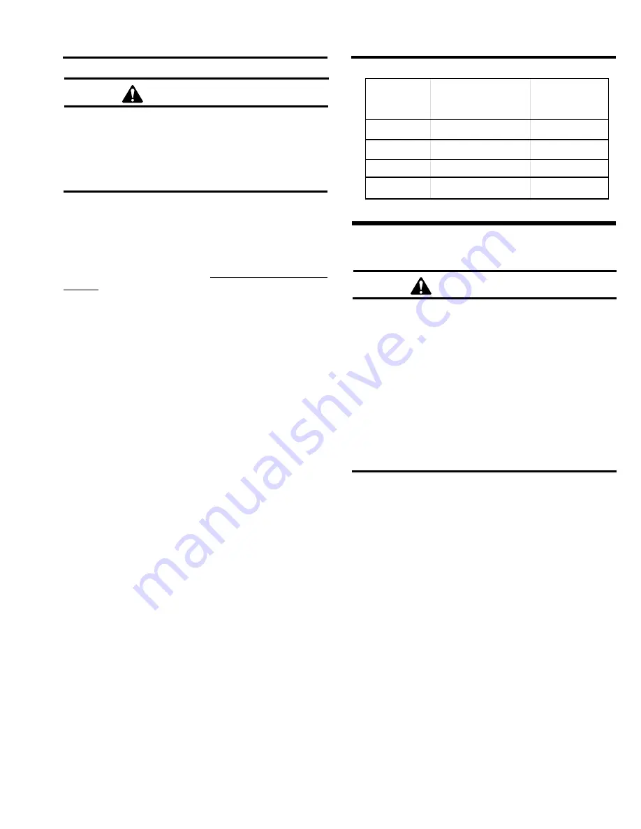
4.2.2
Use the following table to determine the minimum
and maximum pressure setting and maximum respirator
hose length.
Total Hose
Length
Maximum Number
of Hose Sections
Pressure (psi)
Min. Max.
50 feet
1
6
to
10
100 feet
2
8
to
14
200 feet
2
11
to
20
300 feet
3
15
to
20
5.0
OPERATION
WARNING
• With the respirator on, leave the blast area
immediately if any of the following conditions
occur:
• Any part of the respirator system becomes dam-
aged.
• Any air monitoring alarm is activated.
• Airflow into the respirator is reduced or stops.
• Breathing becomes difficult.
• At the first sign of dizziness, nausea, fever,
illness or injury.
• Any contamination is noted by taste, smell or
vision inside the respirator.
• Vision becomes impaired.
• Any irritation is noted.
5.1
Prior to operation, thoroughly inspect and clean
the helmet, breathing tube, respirator hose, air entry ports,
and fittings of all dust and debris. Inspect the helmet
suspension and adjust if necessary per Section 6.1.
5.2
Begin operation of the ambient air pump per the
manufacturer’s instructions.
5.3
Check air pressure at the point of attachment. Set
the pressure between the minimum and maxium pres-
sures assigned in Section 4.2.2.
5.4
Check all safety, and breathing equipment used in
conjunction with the respirator as recommended by the
manufacturer.
5.5
Check respirator hose and connections for tight-
ness and leaks.
5.6
Put the respirator on in a clean non-hazardous
environment, free of contaminants, where the air is safe to
breathe. When putting the respirator on or taking it off,
keep it upright to prevent dust and abrasive from falling
inside.