APOLLO 20 LP SUPPLIED-AIR RESPIRATOR
Page 7
5.7
Position the chin strap so it fits comfortably under
the chin.
5.8
Position the knit cuff on the inner collar so that it fits
snugly around the neck in turtleneck fashion, without any
interference from clothing such as shirt collars. When
correctly positioned the smaller elastic end of the collar
must face up.
WARNING
Correct placement of the inner collar is critical for
providing the protection for which the respirator
is designed. The collar must be positioned and
maintained without any interference from items
such as hair, facial hair, or shirt collars, between
the collar and user’s neck.
5.9
Pull the cape down to fully extend it and connect
the four elastic straps (two on each side) under the arms,
and tighten using the slides provided.
5.10
Put the belt and Constant-Flow Connector on over
the cape. Buckle the belt around the waist, and tighten it by
pulling the belt end through the buckle insert.
5.11
When finished blasting and with cleanup, remove
the respirator in a clean, non-hazardous environment
where the air is safe to breathe.
WARNING
Do not put the respirator on, or store it in a blast
contaminated environment. Do not remove the
respirator in a contaminated environment except
for emergency evacuation when the use of the
respirator hinders escape.
NOTE: The quick disconnect coupling on the end of the
respirator hose is not equipped with a shut-off. Therefore,
if the hose is disconnected from the respirator while the
pump is in operation, air will continue to flow freely from the
hose. After removing the respirator in a clean environ-
ment, the air pump should be shut off.
6.0
ADJUSTMENTS
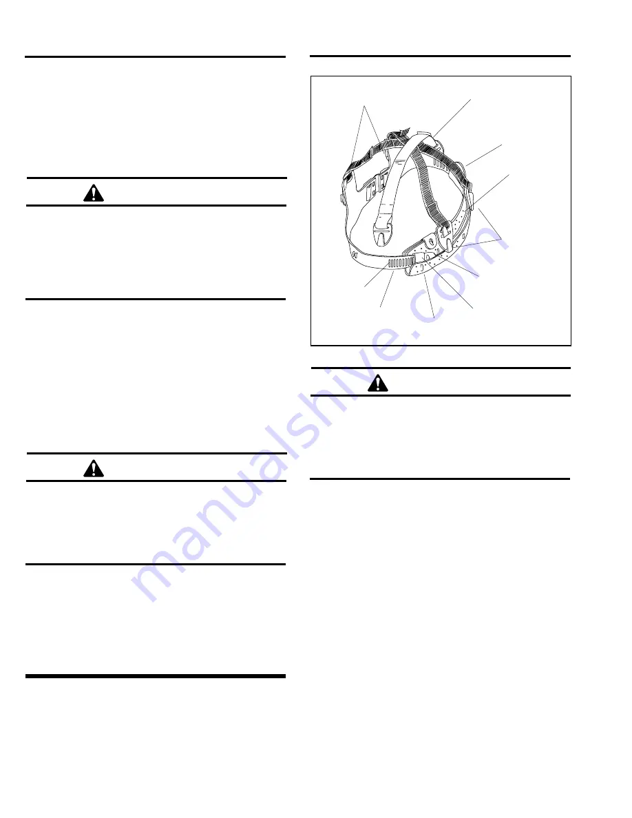
6.1
Helmet Suspension, Adjustment and Re-
placement, Figure 2
WARNING
The suspension maintains a fixed distance be-
tween the head and the helmet. It is critical that
the suspension is properly installed, and ad-
justed as described, to provide maximum head
protection and comfort.
6.1.1
Remove the cape from the helmet per Section 9.4.
6.1.2
Remove and discard the old suspension and
suspension strap by extracting the plastic tabs from the
wedge-shaped clefts in the shell.
6.1.3
Unfasten the vinyl sweatband from the two lower,
outside buttons (A and B in Figure 2).
6.1.4
The suspension fits head sizes 6.5 to 8. Head
sizes are marked on the headband slots. Slide the headband
tongue through the front holder until the desired head size
is reached. It is important that the adjustment be made
evenly on both sides. Press the selected slots firmly onto
the lugs on the front band.
6.1.5
Fasten the vinyl sweatband onto the buttons of the
suspension.
6.1.6
Install the suspension strap before installing the
suspension. Insert the yellow end tabs into the clefts on the
helmet shell. When correctly installed the strap is between
the suspension and helmet shell and above the ears.
Headband
Size Slots
White Plastic
Tabs
(front)
White Plastic Tabs
(rear)
Button B
Suspension Strap
Button A
Vinyl
Sweatband
Head Band
Tongue
Front Holder
Front Band
Lugs
Figure 2.