CLASSIC BLAST MACHINE with TLR-100/300 REMOTE CONTROLS
Page 16
© 2018 CLEMCO INDUSTRIES CORP.
www.clemcoindustries.com
Manual No. 22501, Rev. I 02/18
3.9.6
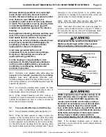
When the machine is empty, release the control
handle lever, open the safety petcock, and open the
choke valve.
3.9.7
If the nozzle was removed, thoroughly inspect
the nozzle holder threads for wear before installing the
nozzle washer and reattaching the nozzle.
3.10 Shutdown
3.10.1
Empty the blast machine per Section 3.9.
3.10.2
When finished emptying the machine and after
cleanup is completed, remove the respirator and
protective clothing outside the respirator-use area, in a
clean environment where the air is safe to breathe.
3.10.3
Close the compressed-air supply valve at the
compressor.
3.10.4
Drain receiver tank, filters, air filters and water
collecting devices, and bleed the compressed-air supply
hose.
3.10.5
Shutdown the compressor.
3.10.6
Cover the blast machine when not in use. Refer
to Section 8.1 for optional cover.
4.0 ADJUSTMENTS
4.1
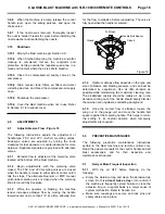
Adjust Abrasive Flow - Figure 16
The following instructions explain the adjustment of
handle-type FSV and LPV (Lo-Pot) metering valves.
Knob-type valves are adjusted by turning the knob
clockwise for less abrasive or counterclockwise for more
abrasive. Separate manuals are provided with alternate
valves.
4.1.1
Abrasive flow is adjusted at the metering valve
located at the bottom of the blast machine.
4.1.2
Begin adjustments with the metering valve
closed. The FSV and LPV metering valves are closed
when the handle is turned to either side of center until it
hits the stops. The alternate Quantum or MPV manual
pinch-tube metering valve is closed when the metering
knob is turned fully clockwise.
4.1.3
While the operator is blasting, the machine
tender increases abrasive flow by moving the handle
toward center no more than 1/4" at a time, allowing time
for the flow to stabilize before readjusting. The valve is
fully open when the handle is centered.
Figure
16
4.1.4
Optimum abrasive flow depends on the type and
size of abrasive and blasting pressure, and can best be
determined by experience. Use as little abrasive as
possible while maintaining the maximum cleaning rate.
The air-abrasive mixture should be mainly air. As a rule,
abrasive coming out of the nozzle should barely discolor
the air when seen against a contrasting background.
4.1.5
Once the correct flow is attained, loosen the
wing nut on the gauge unit and move the handle bolt
spacer against the metering handle. This helps to return
the setting to its original position when temporary
adjustments are required.
5.0 PREVENTIVE
MAINTENANCE
The following preventive maintenance instructions
pertain to the blast machine and remote controls only.
Read the owners manuals for the control handle and all
blast accessories, and for their inspection and
maintenance schedules.
5.1
Daily or More Frequent Inspection
5.1.1
With the air OFF before blasting, do the
following:
Empty the abrasive trap and clean the abrasive-trap
screen. Do this
at least twice a day
or more often if
the machine is frequently cycled. Failure to clean the
abrasive trap on a regular basis is a major cause of
system malfunction. Refer to Section 6.6.
Make sure couplings are secure and lock pins and
safety cables are in place.
Handle Bolt Spacer
Closed
Closed
Full Open


