CLASSIC BLAST MACHINE with TLR-100/300 REMOTE CONTROLS
Page 20
© 2018 CLEMCO INDUSTRIES CORP.
www.clemcoindustries.com
Manual No. 22501, Rev. I 02/18
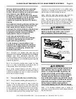
The large spring (not used in 1
valve) is
approximately 2-1/16
long. If it is rusty or
compressed, replace it.
Inspect the valve-plug washer, valve plug, and plug
retainer for damage. Replace all damaged parts.
When reassembling the valve-plug assembly, tighten
the retainer enough to compress the washer, but not
so tight that it causes it to bulge.
Look into the lower opening in the valve body. If the
machined seat is worn, replace the body.
Inspect the bottom cap seal and replace if damaged.
6.3.1.4
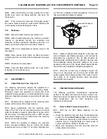
Remove the lower twinline hose connection and
remove the orifice fitting for inspection. Clean the 1/16
orifice and reassemble the connection.
WARNING
F
or proper operation, the orifice fitting must
always be in place. Do not modify it or
substitute another fitting. Altering the orifice
fitting may cause involuntary activation of the
blast machine or some other malfunction, which
could result in serious injury or death.
6.3.1.5
If the top section of the valve requires service,
proceed to Section 6.3.2; otherwise, refer to the
illustration in Figure 17 to reassemble the valve in
reverse order.
6.3.2
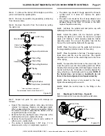
Top Section - Figure 18
6.3.2.1
Remove the control hose and fittings from the
cylinder cap to make sure they are not damaged by a
wrench.
6.3.2.2
Use a pipe wrench to remove the cylinder cap.
6.3.2.3
If the bottom cap has not been removed, remove
the cap and all parts in the bottom section per Section
6.3.1.
6.3.2.4
Insert a wooden hammer handle or similar
object into the bottom of the valve body, push through
the seat area and drive the piston rod up. Doing so will
push the piston out the top of the valve body.
6.3.2.5
Inspect all items for wear and damage:
The piston cup should fit snugly against the cylinder
wall. If it does not, replace the piston assembly.
The piston rod should be free of deep abrasion and
move freely in the rod’s bore. If it is badly abraded,
drags in the bore, or is loose in the bore, replace the
piston assembly.
If the piston rod O-ring is flattened, replace the O-ring.
Inspect the cylinder cap O-ring. Replace it if it is cut
or if it does not fit snugly into the recess at the end of
the threads.
*Items included in service kits.
Figure
18
6.3.2.6
Lubricate the cylinder wall and piston cup with
lightweight machine oil or tool oil.
6.3.2.7
Install the piston into the cylinder. As the piston
cup contacts the cylinder, it may be difficult to press into
place. Do not pound the piston, as that could damage
the cup; make sure the lower lip of the cup does not curl
in or get cut. Rotating the piston while applying thumb
pressure makes assembly easier.
6.3.2.8
Refer to the illustration in Figures 17 and 18 to
reassemble the valve in reverse order.
6.4
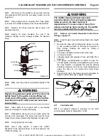
Piston Outlet Valve - Figure 19
Refer to Section 6.5 to service the diaphragm outlet valve.
6.4.1
All service on the outlet valve must be done with
the air OFF and the air supply locked out and tagged
out. It is not necessary to remove the valve from the
blast machine.
6.4.2
Remove the control hose from the valve
bonnet’s elbow adaptor. NOTE: The elbow adaptor and
plug do not need to be removed unless they need to be
replaced.
6.4.3
Using a large wrench, loosen the bonnet from
the valve body until it can be removed by hand.
Elbow Adaptor
Safety Petcock
Does not need to
be removed unless
it is to be replaced.
*Cylinder Cap O-Ring
Cylinder Cap
*Piston Rod O-Ring
Piston Cup
Piston Rod
For replacement parts refer
to Sections
8.9 for 1-1/2" inlet valve and
8.10 for 1" inlet valve.
Piston Assembly
Elbow Adaptor


