CLASSIC BLAST MACHINE with TLR-100/300 REMOTE CONTROLS
Page 8
© 2018 CLEMCO INDUSTRIES CORP.
www.clemcoindustries.com
Manual No. 22501, Rev. I 02/18
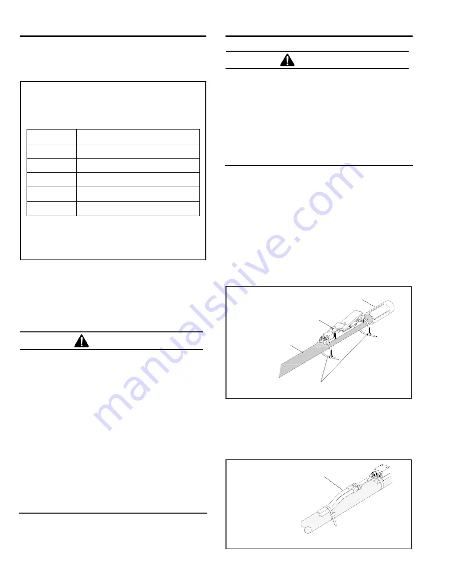
the minimum recommended hose size based on the
nozzle orifice size. A smaller diameter hose could result
in a reduction in nozzle pressure.
AIR LINE RECOMMENDATIONS
BASED ON NOZZLE SIZE
Nozzle
Orifice Size
Recommended Air Supply Line
No. 3, 3/16"
3/4" ID or larger
No. 4, 1/4"
1" ID or larger
No. 5, 5/16"
1-1/4" ID or larger
No. 6, 3/8"
1-1/2" ID or larger
No. 7, 7/16"
2" ID or larger
No. 8, 1/4"
2" ID or larger
Refer to the compressed-air and abrasive
consumption table in Figure 10 for approximate air
consumption.
Figure
6
2.6
Blast Hose and Remote Control Hose
Connections
NOTE: When installing the optional ACS feature,
refer to Section 2.7 for additional instructions.
WARNING
Where two or more blast machines are used in
close proximity, care must be taken when
tracing and connecting control lines and blast
hose. Cross connecting control hose or blast
hose could lead to serious injury, death, or
property damage from unintentional actuation
of a blast machine. To prevent cross
connecting blast hose and control hose, the
hoses should be of equal lengths and the hoses
and blast machine couplings clearly marked,
using optional hose identification kits, stock no.
15890 for use with two blast machines, or stock
no. 15891 for up to four machines. Mark each
hose and corresponding connection per the
instructions supplied with the kit and carefully
trace and verify each connection before
operating.
WARNING
Moist air that freezes can cause blockage at the
control handle or in the control lines. Blockage
can cause involuntary activation of the remote
controls or prevent the controls from
deactivating upon release of the control handle.
This situation could result in serious injury or
death. If remote controls are operated in
freezing or near-freezing weather, install a
Clemco Antifreeze Injector, stock no. 05537, on
the remote control air-supply line.
NOTE: Control hoses come with reusable hose ends.
Excess hose may be cut-to-fit and recoupled; refer to
Section 6.10.
2.6.1
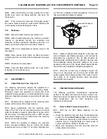
Uncoil the blast hose and lay the 50-foot twinline
hose alongside it.
2.6.2
Band the control handle to the blast hose close
to the nozzle holder, as shown in Figure 7, using the two
nylon ties provided. After the control is firmly attached,
clip the tie ends to avoid snags or interference with the
operation of the control handle.
Figure
7
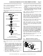
2.6.3
Attach the 50-foot twinline hose to the two
fittings on the control handle, as shown in Figure 8.
Either side of the hose can be attached to either fitting.
When using the ACS option, attach the single-line hose
noted in Section 2.7.
Figure
8
RLX Control Handle
Nozzle Holder
Blast Hose
Nylon Ties
Twinline Control Hose
Either side of the twinline
can attach to either fitting
on the control handle.


