MEDIPULSE 2342se ERGONOMIC SUCTION BLAST CABINET
Page 8
© 2019
CLEMCO INDUSTRIES CORP.
www.clemcoindustries.com
Manual No. 24939, Rev. C, 03/19
right side or left side door. The right side is shown in the
illustrations.
3.3.2
Combine the table assembly and track by sliding
the table assembly rollers into the track channels, as
shown in Figure 7.
NOTE: If the weight of the table and track make it too
heavy to install as an assembly, the track may be placed
in the cabinet to predrill mounting holes, but the table
must also be in place within the rails before fasteners
are installed.
3.3.3
Refer to Figure 8 and center the track and table
assembly inside the cabinet on top of the grate. Make
sure the two angled mounting brackets are facing toward
the door from which the table will slide.
Figure 8
3.3.4
Match drill two 1/2" diameter holes on each side
of the cabinet, using the holes in the mounting brackets
as a template. NOTE: To prevent the track from shifting,
temporarily place a 3/8-NC x 1-1/2" bolt through each
hole after it is drilled.
3.3.5
After the holes are drilled and the table
assembly is placed in the track rails, secure all
fasteners.
Figure 9
3.4
Manometer
The optional manometer kit is listed in Section 9.1.
3.4.1
The manometer measures static pressure.
Consistent static pressure is necessary for precise
media separation, as the reclaimer's efficiency is
achieved by a centrifugal balance of air flow, particle
weight, and size. Reclaimer static pressure is set by
adjusting the outlet damper; refer to Section 5.4 to adjust
static pressure. Refer to Section 5.8 for manometer
instructions.
3.5
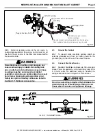
Reclaimer Differential Pressure Gauge
Monitors reclaimer static pressure ‒ Figure 10
3.5.1
The reclaimer differential pressure gauge
continually measures reclaimer static pressure, similar to
a manometer slack tube but it uses a differential
pressure gauge.
3.5.2
The gauge panel, gauge, filter, and panel fittings
come fully assembled; the bushings, snubber fittings,
and tubing are loose. Mount the panel at a location
where it can be easily monitored. A 10-foot length of
tubing is included with the kit, allowing the panel to be
mounted within ten feet of the connections. One
suggestion is to mount it on an accessible side of the
power module.
3.5.3
Mounting holes are on the left and right sides of
the gauge panel. After selecting the location, match drill
holes, and use nuts and cap screws to secure the panel.
3.5.4
Remove the 1/4" pipe plug from the reclaimer
body and install 1/4" x 1/8" bushing and barb fitting, as
shown in Figure 10.
Figure 10
3.5.5
Push the tubing onto the barb fittings on the
gauge and reclaimer, as shown. Cut the tubing to length.
3.5.6
Refer to the differential pressure gauge manual
provided for operation of the gauge.
Urethane Tubing
Differential
Pressure Gauge
Remove plug and install
bushing and barb fitting.
Slide table to center or as
needed to position part for
blasting.
Slide table out for ease
of loading part(s). Not
to exceed 500 pounds.
Match Drill
Match Drill
Angled Mount Brackets


