PIPE-PRO XL™ INTERNAL-PIPE BLAST TOOL
Page 13
© 2017 CLEMCO INDUSTRIES CORP.
www.clemcoindustries.com
Manual No. 27804 Rev A
coupling-flange are shown in the preventive
maintenance section. Refer to Section 7.3.1 to service
the blast head assembly and Section 7.3.2 to service the
backplate coupling-flange assembly.
NOTICE
Removed the tool from the blast hose or lance
and service it in a clean, abrasive-free and dust-
free environment.
Remove the tool from the carriage collar before
performing any service other than the blast
head and nozzles.
8.1
Carriage
8.1.1
Removing the carriage
8.1.1.1
Completely remove the three cap screws
holding the carriage collar to the drive cap and then slide
the carriage from the base tool. Note: If lodged abrasive
prevents removal from the carriage, pry the pieces apart
at the seam between the drive cap and carriage collar
flange, or place a wooden block or similar object against
the quick coupling and rap the block with a hammer to
remove the tool.
8.1.2
Attaching the carriage
8.1.2.1
Insert the base tool, quick coupling first into the
flanged end of the carriage.
8.1.2.2
Align the bolt holes in the drive cap with those in
the carriage collar and insert the plate into the flange.
Align the holes as needed and install the three flat
washers, lock washers, and cap screws to secure.
8.2
Blast Head Assembly, Removal and Inspection
8.2.1
Remove the blast head per Section 7.3.1 and
service the head assembly as needed. Do not yet
reassemble the blast head unless no further service is
required.
8.3 Backplate Coupling Flange Assembly
Removal and Inspection
8.3.1
Remove the backplate coupling flange per
Section 7.3.2 and service the head assembly as needed.
8.3.2
The rear-seals cartridge (sleeve with u-seals and
spacer) may slide out without pressing it. If it slides out,
remove it now; if it does not slide, it will be pressed out
later in Section 8.6. Do not yet reassemble the backplate
and coupling flange unless no further service is required.
8.4
Front Housing and Bearing Removal and
Inspection
8.4.1
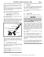
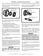
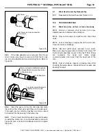
Refer to Figure 22 and unscrew the lock nut
from the axle.
8.4.2
Refer to the following caution and use a 4 mm
hex key to remove the six socket head screws to
separate the front housing from the drive cap and slide
the housing off the axle.
CAUTION
The housing is under moderate spring
pressure. When the retaining screws are
removed, the spring will force the housing
about 1-1/2 inches from the drive cap.
Figure
22
8.4.3
Remove spring bushing and spring from the axle.
8.4.4
Inspect the rim on the head (bearing) side of
spring bushing. When new, the rim extends about 1/16"
from the flange. If the rim is worn beyond 1/32", replace
the bushing.
8.4.5
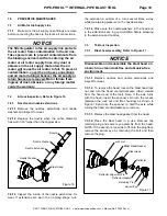
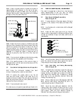
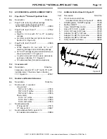
Refer to Figure 23 and remove the felt seal from
the front housing.
Figure
23
8.4.6
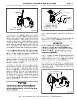
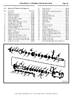
Refer to Figure 24 and remove the bearing from
the front housing; the bearing fits snugly in the housing, if
Axle
Spring Bushing
Spring
Felt Seal
Front Housing
Drive Cap
Socket Head Screw
Front Housing
Lock Nut
Axle

