PIPE-PRO XL™ INTERNAL-PIPE BLAST TOOL
Page 17
© 2017 CLEMCO INDUSTRIES CORP.
www.clemcoindustries.com
Manual No. 27804 Rev A
NOTICE
If the housing makes hard contact before it is
close enough for the screws to engage, do not
force it; internal parts are not aligned. Release
and reapply pressure until the housing slides
into position so it can be secured with screws.
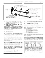
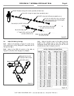
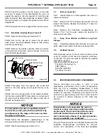
9.3.8
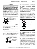
Observe the gap between the bearing housing
and tighten the screws in unison until the flange on the
housing just begins to enter the drive cap. At that time
tighten each screw about half a turn at a time, the
screws should easily turn. If a screw becomes tight,
move to another until the housing is fully seated into the
drive cap.
Figure
32
9.3.9
After the housing is seated in the drive cap,
tighten all screws to secure.
9.4
Rear Bearing, U-Seal Cartridge, and Tube
Casing Reassembly
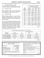
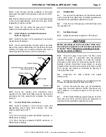
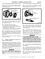
9.4.1
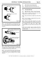
Place the assembled tool on a bench with the
rear of the tube casing facing up as shown in Figure 33.
9.4.2
Fully insert the rear bearing into the end of the
tube casing. Pressing the bearing is usually not needed
if the bearing is inserted straight with no side-cocking.
Figure
33
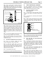
9.4.3
Insert the u-seal cartridge into the tube casing.
The side of the cartridge with the open u-seal faces up.
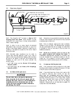
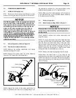
9.5 Backplate Coupling-Flange Reassembly,
Figure 34
9.5.1
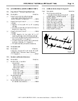
Place the plastic seal-disc into the tube casing.
Note: If the disc is to be reused, make sure the grooved
side faces toward the axle. If the disc is new the sides
are identical; it does not matter how it is installed. The
groove will be formed by the rotating axle.
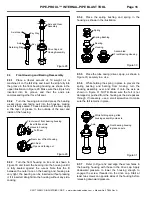
9.5.2
Place the backplate atop the disc and uniformly
tighten the screws to secure. Note: If the end of the axle
extends too far out to prevent installation of the screws,
remove the disc, place a folded paper towel or similar
protective cover over the ridge on the axle, and tighten
the backplate enough to press the axle into the tube
casing. Remove the backplate and protective cover and
reassemble with the seal-disc in place.
Figure
34
9.6
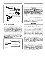
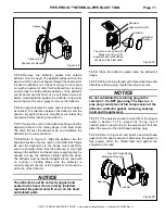
Air Motor and Air Motor Gear Reassembly,
Refer to Figure 35
NOTE: Installation of the air motor requires a narrow 33-
millimeter wrench. If a wrench is not available, one
should be purchased, or machine (or grind) one until it is
narrow enough to fit within the flats.
9.6.1
If the gear was removed or replaced, install it
onto the motor shaft with the set screw end facing
toward the motor as shown in Figure 35. Slide it fully
onto the shaft leaving only enough room to insert a 2-mm
hex key into the set screw. Tighten the screw to secure.
9.6.2
Apply a generous amount of Mobilgrease XHP
462 Moly, Chevron Delo Heavy Duty Moly 3% EP 2, or
equivalent gear grease to the gear teeth, and gear
socket in the drive cap.
Front Bearing Housing
Apply downward pressure on the
bearing housing to start at least
two screws into the drive cap.
Drive Cap
Bearing and Cartridge
Installed in Tube
Assembled U-Seal Cartridge
The open side of u-seal faces up
Bearing
Tube
Backplate with Coupling
Plastic Seal-Disc
Tube Casing

