background image


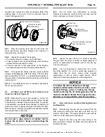
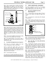
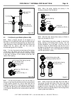
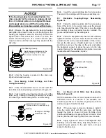
PIPE-PRO XL™ INTERNAL-PIPE BLAST TOOL


Page 4 


© 2017 CLEMCO INDUSTRIES CORP.  

  www.clemcoindustries.com  

  Manual No. 27804 Rev A 

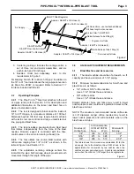
3.2 

Nozzle Stand-Off-Distance Tables 


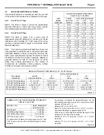
The stand-off distance is the distance from the exit end 
of the nozzle to the inside surface (diameter) of the pipe. 

 
3.2.1 

For 16" to 31" Pipe


3.2.1.1

 The table in Figure 4 shows the approximate 

stand-off distances of short and long venturi nozzles 
when blasting pipe diameters between 16" and 31".  
 

3.2.2 

For 32" to 60" Pipe 


3.2.2.1 

The table in Figure 5 is a quick view of 

approximate stand-off distance for nozzles and nozzle 
extensions when blasting 32" to 60" pipe. When more 
precision is needed refer to Figure 6 to calculate nozzle 
stand-off distances. 
 

3.2.3


The nozzles and stand-off distances shown are 

only guidelines to assist the user in choosing nozzle type 
and orifice diameter; it does not show the nozzle to use 
with a given pipe diameter. Usually the minimum stand-
off distance is about four inches; maximum distance is 
generally between 8" and 16" but depends on nozzle 
orifice size (usually determined by the volume of 
compressed air available), nozzle pressure, surface 
condition, and degree of cleaning required. 


NOZZLE STAND-OFF-DISTANCE 

FOR 16" to 31" ID PIPE 


PIPE 

SHORT 

LONG VENTURI NOZZLE 

INSIDE VENTURI 

1/4" 

5/16" 3/8" 

DIAMETER NOZZLE Orifice 

Orifice 

Orifice 

16" 3-3/4" 

1-3/4" 

1-1/4" 

N/A 

17" 4-1/4" 

2-1/4" 1-3/"4  3/4" 

18" 4-3/4" 

2-3/4" 2-1/4"  1-1/4" 

19" 5-1/2" 

3-1/4" 

3" 

2" 

20" 6" 

4" 

3-1/2" 

2-1/2" 

21" 6-1/2" 

4-1/5" 

4" 

3" 

22" 7" 

5" 

4-3/4" 

3-3/4" 

23" 7-3/4" 

5-1/2" 5-1/4"  4-1/4" 

24" 8-1/4" 

6-1/2" 5-3/4"  4-3/4" 

25" 9" 

6-3/4" 

6-1/2" 

5-1/2" 

26" 9-1/2" 

7-1/2" 

7" 

6" 

27" 10" 

8" 

7-1/2" 

6-1/2" 

28" 10-1/2" 

8-1/2" 

8" 

7" 

29" 11-1//4" 

9" 

8-3/4" 

7-3/4" 

30" 11-3/4" 

9-3/4" 9-1/4"  8-1/4" 

31" 12-3/4" 

10-1/4" 9-3/4"  8-3/4" 


Figure 4 


NOZZLE STAND-OFF DISTANCE for 32"  TO 60" ID pipe 


LONG VENTURI NOZZLE 

PIPE INSIDE 

SHORT  

1/4" 

5/16" 

3/8" 

DIAMETER VENTURI 

NOZZLE Orifice Orifice  Orifice 

32" to 36" W/O Extensions 

13" to 15-1/4" 

10-3/4" to 13" 

10-1/2" to 12-3/4" 

9-1/2" to 11-3/4" 

32" to 36" W/6" Extensions 

7" to 9-1/2" 

4-3/4" to 7" 

4-1/2" to 6-3/4 

N/A 

37" to 47" W/6" Extensions 

9-3/4" to 15-1/2" 

7-3/4" to 13-1/5" 

7-1/4" to 13" 

6-1/4" to 12" 

48" to 60" W/12" Extensions 

10" to 17" 

8" to 15" 

7-3/4" to 14-3/4" 

6-3/4" to 13-3/4" 

53" to 60" W/18" Extensions 

7" to 11" 

5" to 9" 

4-1/2" to 8-3/4 

3-1/2" to 7-3/4" 


Figure 5 


FORMULA TO CALCULATE NOZZLE STAND-OFF 

FOR 32" to 60" PIPE 


NOZZLE TYPE 

BASE  DIMENSION 
@ 32” DIA. PIPE 

Short Venturi 


13 Inches 

1/4" Orifice Long Venturi 


11 Inches 

5/16" Orifice Long Venturi 


10-1/2 Inches 

3/8" Orifice Long Venturi  

9-1/2 

Inches 


To obtain stand-off distance for pipe larger than 32", add 
0.58" for every inch over 32 and subtract length of nozzle 
extension. 


For example, to calculate the stand-off distance of a 48 
inch diameter pipe when using a No. 5 long venturi nozzle 

Subtract 32" from 48" = 16" 
Multiply 0.58" x 16 = 9.28 (9-1/4") 
Add 9-1/4" to No. 5 base dim. (9.1/4 + 10-1/2" = 19-3/4") 

The stand-off distance is approximately 19-3/4". 


When using a nozzle extension subtract the length of the 
extension. In the case of the example: 

Subtract 6" for a 6" extension (19-3/4" - 6" = 13-3/4" 
stand-off). 


Subtract 12" for a 12" extension (19-3/4" - 12" = 7-3/4" 
stand-off). 


Figure 6 


Summary of Contents for PIPE-PRO XL

Page 1: ...s equipment until you have READ this MANUAL and YOU UNDERSTAND its contents These WARNINGS are included for the health and safety of the operator and those in the immediate vicinity If you are using a...

Page 2: ...o potential physical injury hazards Obey all safety messages that follow this symbol to avoid possible injury or death NOTICE Notice indicates information that is considered important but not hazard r...

Page 3: ...2 1 1 The primary components of the Pipe Pro XLTM tool are shown in Figure 1 and Figure 2 Figure 1 shows the basic tool Figure 2 shows the items in the air motor control hose kit The control hose kit...

Page 4: ...within the pipe Soft carriage wheels provide smooth movement through the length of the pipe 3 0 ANCILLARY EQUIPMENT REQUIREMENTS 3 1 Blast Machine and Accessories 3 1 1 The blast machine should be of...

Page 5: ...21 6 1 2 4 1 5 4 3 22 7 5 4 3 4 3 3 4 23 7 3 4 5 1 2 5 1 4 4 1 4 24 8 1 4 6 1 2 5 3 4 4 3 4 25 9 6 3 4 6 1 2 5 1 2 26 9 1 2 7 1 2 7 6 27 10 8 7 1 2 6 1 2 28 10 1 2 8 1 2 8 7 29 11 1 4 9 8 3 4 7 3 4 3...

Page 6: ...e operation of the air motor moisture in the air motor air line could will accelerate wear on the motor 3 4 2 Dust or abrasive ingress will cause extensive damage to the air motor The filter pressure...

Page 7: ...or out of the pipe while blasting A shroud may be built at the ends of the pipe to contain blasting or any voids at the ends of the pipe can be blasted using a standard blast nozzle 5 2 Assemble Cente...

Page 8: ...be at least 3 8 ID Increase the inside diameter to 1 2 when using more than one section of supply hose multiple connections of 3 8 hose could restrict air volume needed to operate the air motor NOTIC...

Page 9: ...2 12 4 45 26 15 7 8 23 12 4 1 2 46 26 16 3 8 24 12 5 47 26 16 7 8 25 12 5 1 2 48 26 17 3 8 26 12 6 1 8 49 26 17 7 8 27 12 6 5 8 50 26 18 3 8 28 12 7 1 8 51 26 18 7 8 29 12 7 5 8 52 26 19 3 8 30 12 8 1...

Page 10: ...minum or 00566 brass couplings 6 0 OPERATION 6 1 Set up and load abrasive into the blast machine and connect air lines blast lines and blast equipment as described in the applicable operation manuals...

Page 11: ...f extensions are worn to an oblong shape turn the extension a quarter of a turn several times a day while maintaining pressure on the nozzle washer 7 2 1 4 Make sure the nozzle washers in the head and...

Page 12: ...and head some realigning may be needed to keep the deflector straight within the head The deflector must be inserted straight into the head with no cocking or binding Make sure the deflector is corre...

Page 13: ...4 1 Inspect element in filter regulator and clean or replace as needed 7 4 2 Remove the front housing per Section 8 4 and inspect the bearing Replace the bearing if it does not turn smoothly 7 4 3 Re...

Page 14: ...ead per Section 7 3 1 and service the head assembly as needed Do not yet reassemble the blast head unless no further service is required 8 3 Backplate Coupling Flange Assembly Removal and Inspection 8...

Page 15: ...tion and inspection before removing the axle or drive cap NOTICE Do not use a pipe wrench or similar tool to remove the air motor doing so will damage the motor 8 5 1 The air motor has left handed or...

Page 16: ...E MAINTENANCE REASSEMBLY The order of reassembly is shown for a tool that was totally disassembled If the tool was not totally disassembled skip the sections that do not apply 9 1 Rear Seals Cartridge...

Page 17: ...thout any side cocking 9 3 4 Place the spring bushing and spring in the housing as shown in the illustration Figure 30 9 3 5 Place the tube casing drive cap up as shown in Figure 31 securely in a vice...

Page 18: ...rooved side faces toward the axle If the disc is new the sides are identical it does not matter how it is installed The groove will be formed by the rotating axle 9 5 2 Place the backplate atop the di...

Page 19: ...last head per Section 7 3 1 10 0 TROUBLESHOOTING 10 1 Blast head does not turn or turns too slowly 10 1 1 Volume or pressure of air at motor is too low Adjust pressure to between 80 and 90 psi 10 1 2...

Page 20: ...11 2 Conversion kit Item Description Stock No Large pipe converts 16 to 31 tool to 16 to 60 includes items 1 thru 6 as shown in Section 11 7 Figure 40 28047 11 3 Nozzles and Nozzle Extensions Item Des...

Page 21: ...foot 28583 18 Adaptor 1 8 x 8 mm air motor inlet tube 28584 19 Adaptor 1 4 x 8 mm air motor outlet tube 28585 20 Screw 4 x 6 mm set 90592 21 Gear air motor 27808 22 Tube casing 27816 23 Screw 6 x 18 m...

Page 22: ...on kit converts 16 to 31 centering carriage to 16 to 60 carriage includes items marked with 28047 1 Extension rail set of three w wheels 28856 2 Extension rail does not include wheels 27806 3 Leg carr...

Reviews: