PIPE-PRO XL™ INTERNAL-PIPE BLAST TOOL
Page 7
© 2017 CLEMCO INDUSTRIES CORP.
www.clemcoindustries.com
Manual No. 27804 Rev A
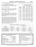
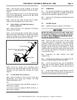
Figure
10
5.3 Air
Motor
Connections
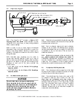
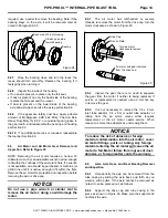
5.3.1
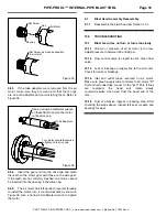
Assemble and attach the inlet and outlet tube
connectors as shown in Figures 1 and 2. The inlet tube
connector with filter must be connected to the green inlet
tube. To attach the connectors to the tubing, simply insert
the tubing through the collar and push until it bottoms out
in the fitting. Tug on the tube to make sure it is secured.
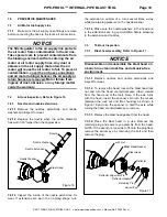
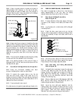
To release the connectors, refer to Figure 11. An arrow on
the inlet tube shows the direction of air flow; the green
tube, with the arrow pointing toward the tool is the inlet,
the red tube is the outlet.
NOTE: If the arrow or tubing
are removed or damaged, use a flashlight to look into
the carriage collar; the green inlet tube goes to the
"R" port on the air motor, the red outlet tube goes to
the "EXH" port on the motor.
Figure
11
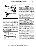
5.3.2
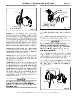
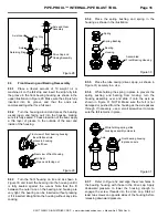
Refer to Figure 12 and set up an air supply to
the 3/8" x 50' air hose provided with the tool.
NOTICE
To reduce the risk of abrasive ingress into the
air motor, cover air motor fittings and hose ends
when disconnecting air hoses from the tool. Any
dust or abrasive from the air supply, which
enters the air motor, will cause the air motor to
fail. Motor failure from ingress of dust, abrasive,
or any foreign matter voids the warranty.
5.3.3
The air supply line to the filter/regulator inlet and
the smallest inside diameter of any connections must be
at least 3/8" ID. Increase the inside diameter to 1/2"
when using more than one section of supply hose;
multiple connections of 3/8" hose could restrict air
volume needed to operate the air motor.
NOTICE
A combination filter/pressure regulator is
provided and must be installed in the air motor
air supply line. The filter removes particles that
could damage the motor. The pressure regulator
reduces pressure to below 100 psi. Maximum
operating pressure for the air motor is 100 psi.
5.3.4
Attach one 3/8" air hose from the air supply
(filter/regulator) to the air motor inlet-tube connector, as
shown in Figure 12. The inlet tube is identifiable by its
green color and inline filter. The hose must be long
enough to reach between both ends of the pipe being
blasted; attach additional lengths of hose as needed.
5.3.5
Attach the flow-control assembly to one end of
the second 3/8" hose and attach the other end to the
tube connector on the red outlet tube from the air motor;
this hose must also be long enough to reach between
both ends of the pipe being blasted.
5.3.6
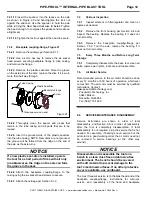
The flow-control valve should be placed at
approximately the same location as the blasting control
handle. Air flow through the motor begins when the flow-
control valve is opened, the more the flow-valve is
opened, the faster the head rotates. The head stops
rotating when the flow-control valve or shutoff valve is
closed. The flow-control valve is opened or closed, as
required to rotate the blast head at 40-60 rpm.
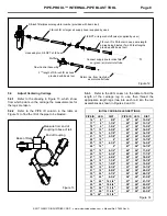
Push collar in to release tubing
Pull tubing straight out
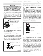
Retaining Collar
Collar Couplings
8 mm Cap Screw
Rail Extension
Rail
8 mm Lock Nut
Make sure all legs are
inserted from the same side

