MEDIA RECLAIMER / SEPARATOR
Page 10
© 2005 CLEMCO INDUSTRIES CORP.
•
www.clemcoindustries.com
•
Manual No. 23438
•
Rev. E
Figure
8
5.4.4
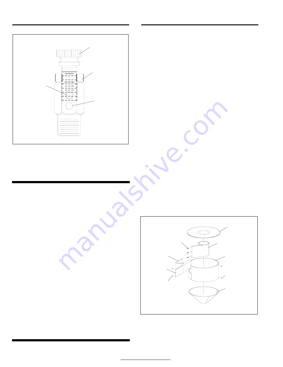
If media flow is too light, decrease air in the
mixture by turning the metering screw in (clockwise when
viewed from the top) covering more of the holes so less air
enters the media hose. Tighten the locking nut finger-tight
to maintain the setting.
6.0 PREVENTIVE
MAINTENANCE
6.1
Clean the debris screen daily: To clean, turn the
exhauster off, open the media fill door and remove
screen. Empty the screen and replace it, making sure it
is securely re-attached to the inner cone.
6.2
Check metering valves for obstructions: This is
especially important on reclaimers used with automated
shot peening equipment, where the nozzle flow may not
be seen. Check flow through the clear, metering valve
tube. Blockage occurs in this area if the debris screen is
improperly installed or is detached, or when the
metering valve needs adjusting.
6.3
Periodically check media hose for soft spots.
Replace the hose as soon as soft spots are noted. Worn
hose could collapse, and restrict media flow.
6.4
Periodically check the reclaimer inlet and outlet
pipes, flex hose, and ducting for wear, and replace as
required.
6.5
Check optional rubber liners. Replace liners
when the rubber is worn-through.
7.0 SERVICE
MAINTENANCE
7.1
Replacing Wear Plate
7.1.1
Remove the inlet adaptor and old wear plate.
The wear plate is held in place by screws attached from
the outside of the reclaimer.
7.1.2
Angle the new wear plate into reclaimer inlet
until it is in position with the straight end at the reclaimer
inlet. Using a board or similar object as leverage, pry the
wear plate against the inner wall and top of the
reclaimer, and install sheet metal screws to hold in
place. Caulk any gaps or voids around the top of the
wear plate to prevent rapid wear.
7.2
Replacing Optional Rubber Liners, Figure 9
Installation Note: When installing the liners, ensure that
seams are aligned. The final assembly must be smooth
and free of protrusions, edges, and gaps. Any edges will
disrupt the air flow, causing wear, and affect the
reclaimer’s media cleaning efficiency.
7.2.1
Remove the inlet and outlet flex hoses.
7.2.2
Remove the bolts located next to the inlet
adaptor that secure the end of the inlet baffle to the
reclaimer weldment.
7.2.3
Remove the socket head screw that secures the
inlet-top liner to the reclaimer top.
Figure 9
7.2.4
Remove the bolts securing the reclaimer top,
and remove the top, along with the top liner and inlet
baffle. NOTE: Inlet baffles are tack-welded to the inner
tube. Before removing the baffle, make an alignment
Adjusting Screw
Lower holes
fully open
Locking Nut
Upper holes
fully closed
Top Liner
Lined Inlet Baffle
Side Liner
Sump Liner
Self-Drilling
Screws
Baffle Bolts
Enter from outside
Inlet-Side
Liner
Self-Drilling
Screws
Inlet-Top
Liner


