MEDIA RECLAIMER / SEPARATOR
Page 4
© 2005 CLEMCO INDUSTRIES CORP.
•
www.clemcoindustries.com
•
Manual No. 23438
•
Rev. E
without the inlet baffle. The adjustable vortex cylinder
should be installed when using 200-mesh and finer
media.
1.8.9 Lightweight
Media:
When using plastic media,
and most agricultural media, the inlet baffle of the
reclaimer may need to be removed. Consult the factory
before proceeding with this option. Reclaimers can be
ordered from the factory without the inlet baffle. The
adjustable vortex cylinder should be installed when
using lightweight media.
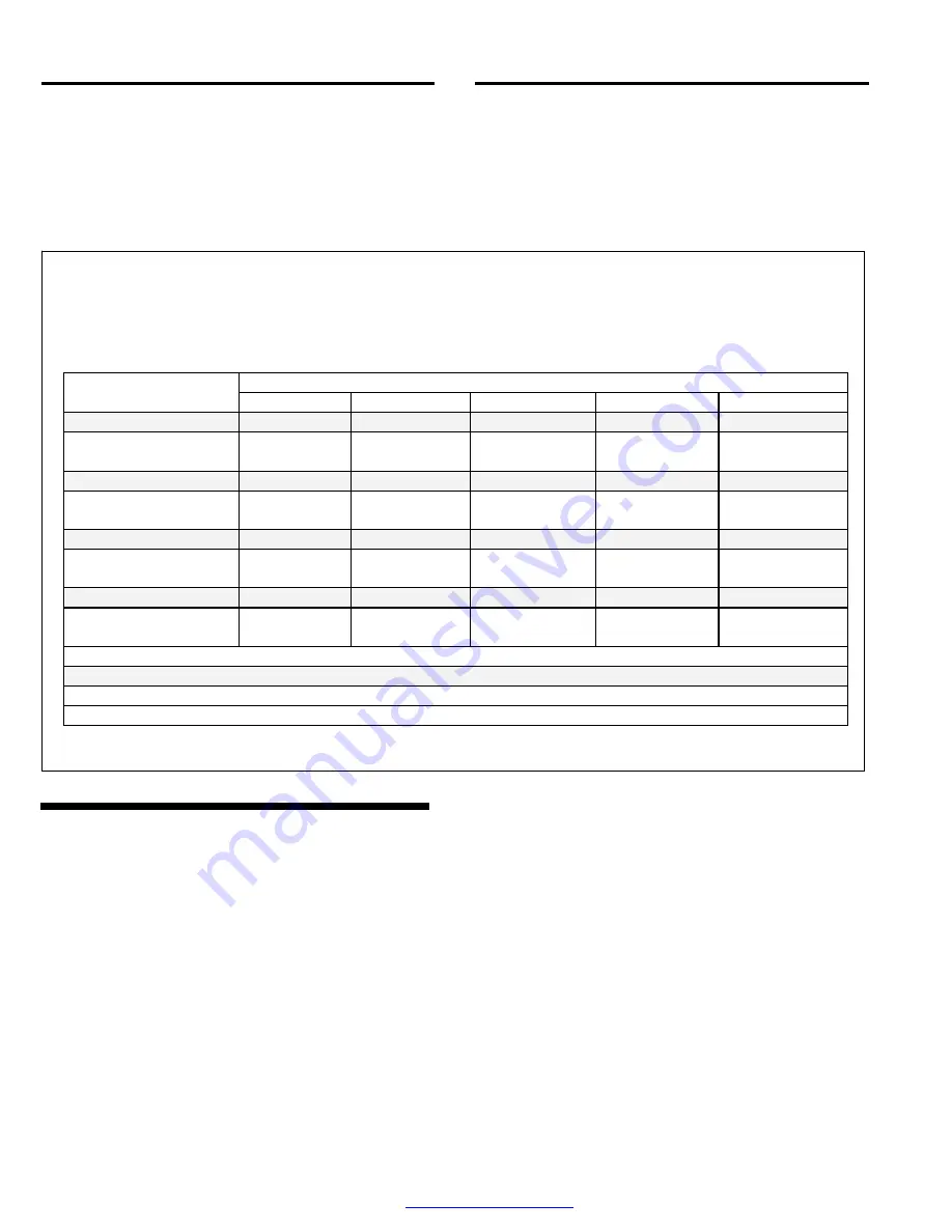
Media sizes shown below are guidelines only, and based on average conditions, such as contamination of parts
being cleaned, humidity, media friability, reclaimer loading rate, etc. Any air restrictions external of the reclaimer
will affect usable media size. Media finer than those shown may decrease visibility in the blast enclosure, and at
some point carryover to the dust collector. Media coarser than those shown may be too large for the reclaimer to
recover from the enclosure.
MEDIA TYPE
RECLAIMER SIZE
STEEL GRIT
STEEL SHOT
PLASTIC
GLASS BEAD
ALUM. OXIDE
900 cfm with 5" inlet
40 & finer
170 & finer
Do not use
Do not use
16 to 36
900 cfm with 6" inlet
Do not use
Do not use
*12 to 40
#6 to #12
*
#13
46 to 200
* 220 to 320
1200 cfm with 6” inlet
40 & finer
170 & finer
Do not use
Do not use
16 to 60
1200 cfm with 7” inlet
Do not use
Do not use
*All sizes
#6 to #12
*
#13
46 to 200
* 220 to 320
1800 cfm with 7” inlet
25 & finer
280 & finer
Do not use
Do not use
16 to 60
1800 cfm with 8” inlet
Do not use
Do not use
*All sizes
#6 to #12
*
#13
46 to 200
* 220 to 320
2500 cfm with 8” inlet
25 & finer
280 & finer
Do not use
Do not use
16 to 60
2500 cfm with 10” inlet
Do not use
Do not use
*All sizes
#6 to #12
*
#13
46 to 200
* 220 to 320
Shaded lines represent reclaimers with reduced sized inlet
Non shaded lines represent standard reclaimers
* To utilize these size media baffle is removed from the reclaimer
Figure 2
2.0 INSTALLATION
Installation Notes:
The externally adjustable vortex
cylinder and exhauster can be rotated, to align the
reclaimer inlet, vortex adjustment handle, and
exhauster outlet, to the most efficient positions.
Determine the best location for all components, and
position all segments before final assembly.
2.1 Placement
2.1.1
General arrangement drawings are provided on
job orders (equipment built around user specifications).
Place the reclaimer as close as possible to the
orientation or as shown on the floor plan of those
drawings.
2.1.2
Position the reclaimer to provide full access to
load and unload media, and to service the vortex
cylinder and metering valves. For optimum efficiency
and the least amount of equipment wear, the reclaimer
should be located directly behind, and as close as
possible the cabinet or room enclosure.
2.1.3
Rotate the reclaimer, to enable connection of
the inlet flex hose with as few bends as possible.
2.1.4
Rotate the externally adjustable vortex cylinder
and exhauster, to align the vortex adjustment handle,
and exhauster outlet, to the most efficient positions.


