PULSAR
®
PLUS 55-S SUCTION BLAST CABINET
Page 21
© 2021 CLEMCO INDUSTRIES CORP.
www.clemcoindustries.com
Manual No. 30423
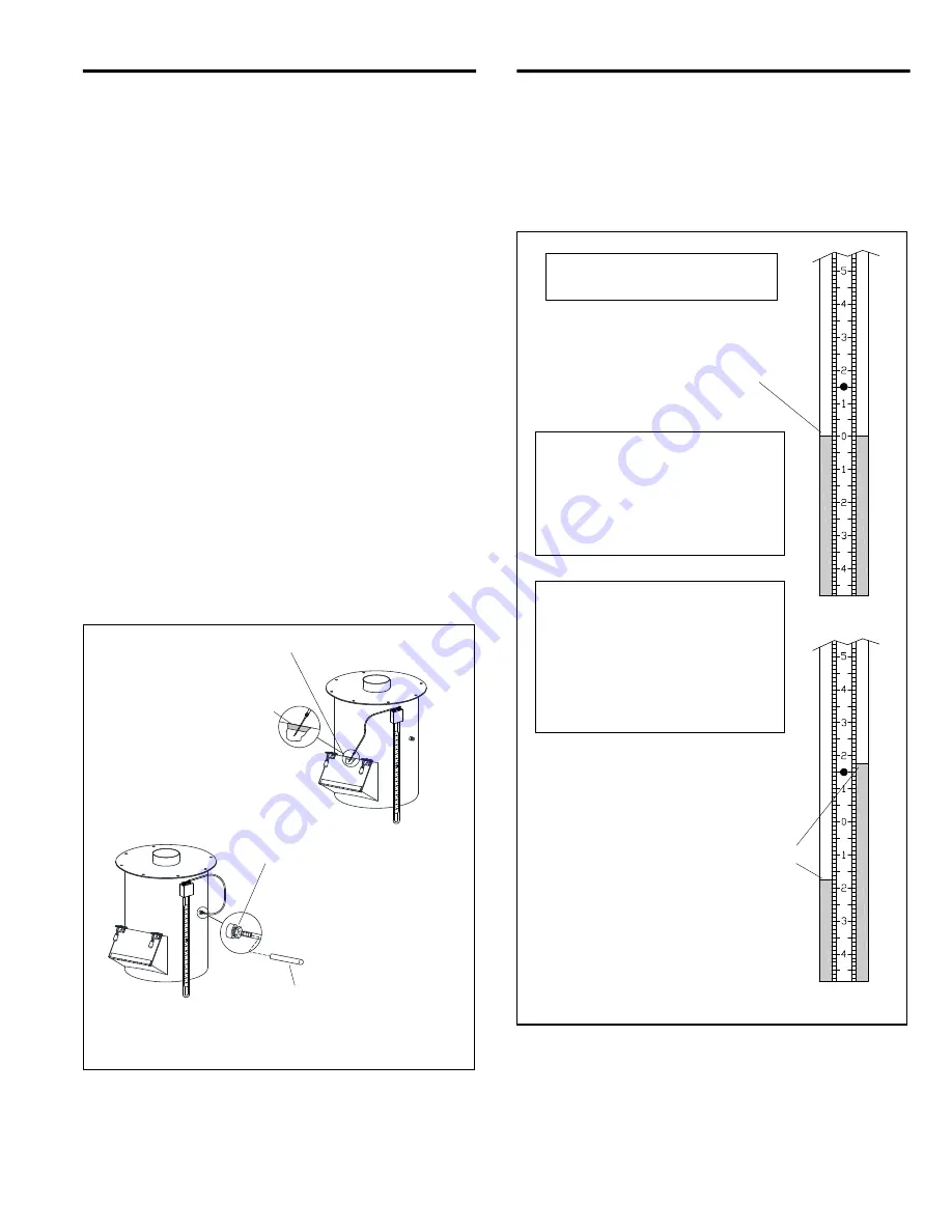
5.10.6 Setup to take occasional readings
5.10.6.1
A
n
eedle used to take occasional readings is
provided with the manometer kit. Leave the needle
protector on the needle and insert the needle into the
unused end of the manometer tubing. The ends of the
tubing must fit tightly on the manometer and needle, as
leaks will give inaccurate readings. Open the reclaimer’s
media fill door, remove the needle protector, and place
the needle so the point is inside the door opening.
Carefully close the door on the needle. The side of the
needle embeds into the rubber door gasket, as shown in
Figure 27, creating an airtight seal. Proceed to
Paragraph 5.10.8 to take readings.
5.10.7
Setup to take frequent readings
5.10.7.1
Remove the pipe plug from the 1/4" NPT
coupling located on the side of the reclaimer. Apply
thread sealant to the male threads of the 1/4" NPT barb
fitting provided with the manometer, and install the fitting
into the coupling, as shown in Figure 27.
5.10.7.2
Place the unused end of the manometer tubing
over only the first tapered barb on the barb fitting;
pushing the tubing all the way onto the barb may make it
difficult to remove. Proceed to Paragraph 5.10.8 to take
readings.
Figure 27
5.10.8
Taking readings
5.10.8.1
Open cabinet doors and turn the exhauster ON.
The negative (static) pressure moves fluid in the tube.
NOTE: Readings must be taken with the cabinet
doors open and with the exhauster running.
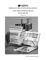
Figure 28
5.10.8.2
To find the static pressure, add the number of
inches the fluid travels up one column to the inches the
fluid travels down the other column. Refer to the
example in Figure 28.
To take occasional readings,
refer to Section 5.10.6.
Position the needle so the
point is inside the reclaimer
door opening. Carefully close
the door on the needle.
Media Fill Door
The reclaimer is shown for reference,
the style may vary.
To take frequent readings,
refer to Section 5.10.7.
Remove the plug and
install the fitting provide
with the manometer, into
the coupling, as shown.
Vinyl Barb Cap
The manometer must be vertical
when taking pressure readings.
With the exhauster OFF,
slide the rule to align the
zero (0) with the fluid level.
To obtain the pressure reading:
With the exhauster ON, add the
number of inches the fluid travels up
the column to the inches the fluid
travels down the other column. The
total is the static
-
pressure reading.
Alternate Zeroing:
Some may find
it easier to read the column by
starting the exhauster and then
sliding the zero on the rule even
with either the high or the low
column. The static pressure is how
far the fluid travels up or down the
other column.
In the example shown, fluid traveled up
the right column 1-3/4",
and down the left column 1-3/4".
Static pressure is determined by adding
the columns together. In the example,
the static pressure is 3-1/2 ".


