background image


4 / 11 

No. 999-1009, Min’an Avenue, Xiang’an                                                                                                                              18/20 Duerdin , 

Xiamen China 361006                                                                                                                                                            Clayton VIC 3168 
Tel: +86-592-5781288                                                                                                                                                  Tel: +61-3-90176688 

Fax: +86-592-5782298                                                                                                                                                Fax: +61-3-90176668 
Email: 

sales@clenergy.com.cn

                                                                                                                  Email: 

sales@clenergy.com.au


Website: 

www.clenergy.com.cn

                                                                                                              Website: www.clenergy.com.au 

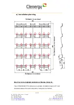
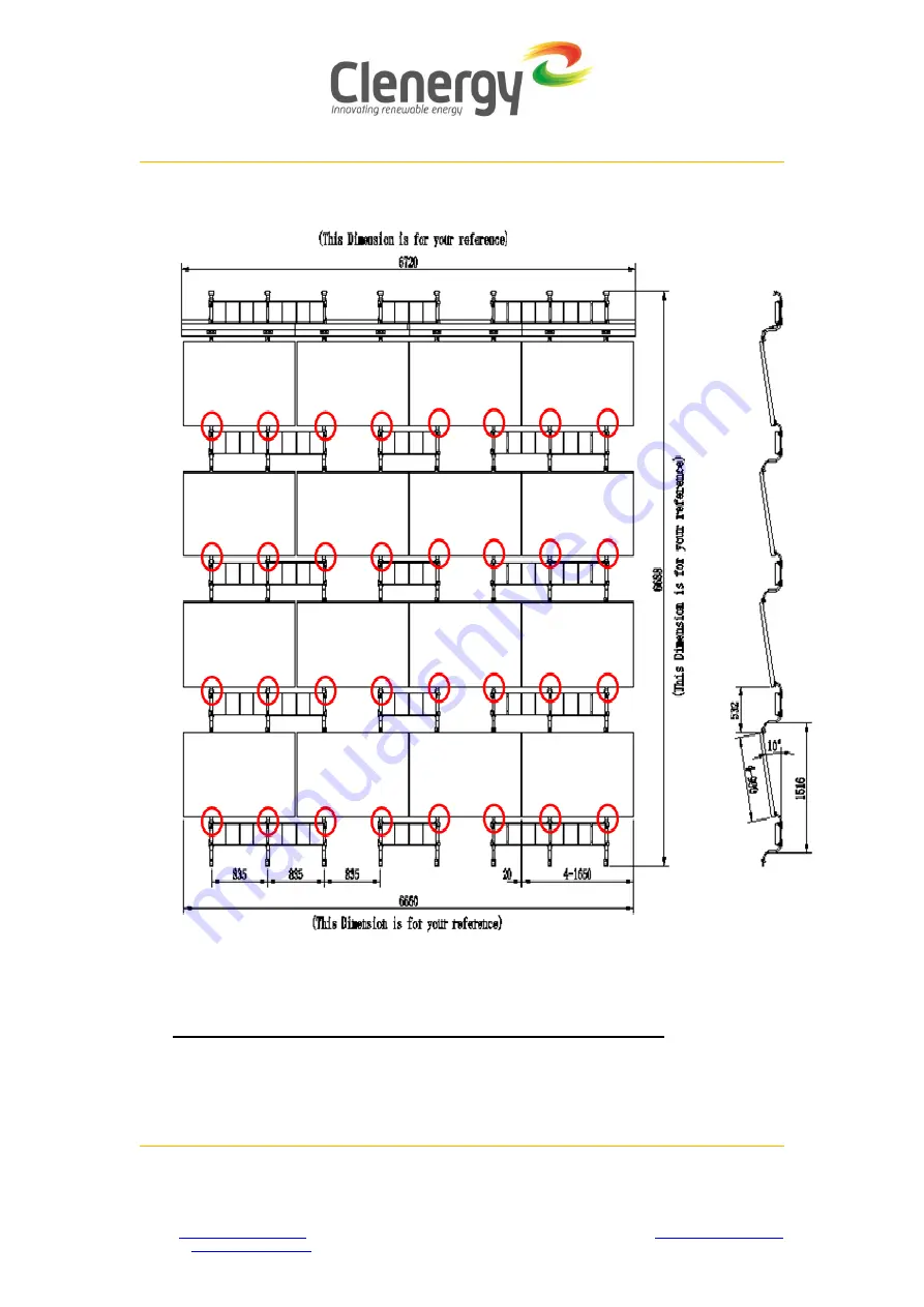
a)  Installation planning 


Note: Red circles highlight installation of Module Clamp 40;   

Take 1650x990x40 PV module as an example. Installation angle is 10° and 

distance between front and rear parts of component is 532mm.   

Summary of Contents for PV-ezRack SolarBase

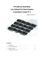
Page 1: ...PV ezRack SolarBase Low Ballast Flat Roof System Installation Guide V1 4 NO PZ30 IM01 14 Content 1 Introduction 1 2 Tools Components 2 3 System overview 3 4 Installation Instructions 6...

Page 2: ...h reduces cost and improves efficiency during installation Please review this manual thoroughly prior to installing PV ezRack SolarBase This manual provides supporting documentation for building permi...

Page 3: ...Components 2 1 Tools 6mm inside hexagonal spanner Electric tool 5m tape Marking pen Torque spanner string Socket spanner Note tools in the figure are only used for rack system not included in supply s...

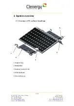
Page 4: ...el 61 3 90176688 Fax 86 592 5782298 Fax 61 3 90176668 Email sales clenergy com cn Email sales clenergy com au Website www clenergy com cn Website www clenergy com au 3 System overview 3 1 Overview of...

Page 5: ...8 Fax 61 3 90176668 Email sales clenergy com cn Email sales clenergy com au Website www clenergy com cn Website www clenergy com au a Installation planning Note Red circles highlight installation of M...

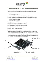
Page 6: ...seizing in the threads 2 General installation instructions 1 Apply force to fasteners in the direction of thread 2 Apply force uniformly to maintain required torque 3 Professional tools and tool belt...

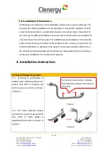
Page 7: ...rom those shown in this guide The installation process detailed in this instruction guide remains the same regardless of the component size In case you need to do any on site modifications or alterati...

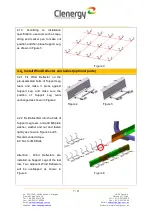
Page 8: ...shown in Figure 3 Figure 3 4 2 Install Wind Deflector and ballast optional parts 4 2 1 Fix Wind Deflector on the pre assembled bolts of Support Leg team and make it press against Support Leg and make...

Page 9: ...eflector tightly as shown in Figures 7 and 8 Recommended torque 8 9 N m for U bolt M8 58 4 2 4 After Wind Deflector and Ballast bar are installed load ballast orderly Ballast height should be no more...

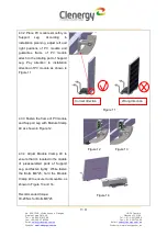
Page 10: ...le and guarantee frame of PV module attach to the rotating part of Support Leg Pay attention to installation direction of PV module as shown in Figure 11 4 3 3 Fasten the frame of PV module and Suppor...

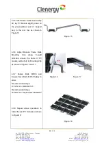
Page 11: ...htly down on the preassembled part of Support Leg in the rear row as shown in Figure15 4 3 6 Adjust Module Frame Back Mounting Clip along fore aft direction ensure the frame of PV module will be held...

Page 12: ...www clenergy com au 4 4 Install Grounding Lug 4 4 1 Fix the Grounding Lug on Ballast Bar of the longest row along vertical direction as shown in Figure 19 install one Grounding Lug per row and fasten...

Reviews: