background image

1

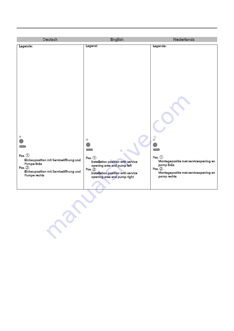
Legende:

Die abb. ist ein Montagebeispiel, es 
sind noch weitere einbausituationen 
möglich.

a1, a2...  mögliche serviceöffnungen für 

technik (abmessung 600 x 600 mm)

a1  Die serviceöffnung a1 ist 

empfehlenswert, das erreichen der 
technik ist hier optimal.

X  empfohlener Bereich für den Kalt- 

(rechts) und den Warmwasseranschluss 
(links) Dn 15.

y  empfohlener Bereich für den 

Wasserablauf Dn 50 (Boden: oberkante 
anschlussmuffe bündig standfläche 
Wannenfüße)

z  anschluss der elektrischen zuleitung 

und des Potentialausgleichs (erdung)* 
im gesamten Bereich der Wand 
möglich. ausreichend abstand zu den 
außenkanten einhalten!

Wannenfuß
Poolmaster Basic

  haltegriff

Pos. 

Einbauposition mit Serviceöffnung und 
Pumpe links

Pos. 


Einbauposition mit Serviceöffnung und 
Pumpe rechts

*

Querschnitt von mindestens 4 mm

2

Deutsch

WellPool 430 / Masse / technIsche DetaIls

Legend:


the picture is an installation example, 
it‘s possible to install other situations.

a1, a2...  possible service opening area for 

maintenance (dimensions 600 x 600  
mm)

a1  service opening position a1 is strongly 

recommended. It provides a optimal 
part accessibility.

X  recommended position for cold 

water connection (right) and hot water 
connection (left) Dn 15.

y  recommended position for the water 

drainage Ø 50 (floor: upper rim of 
connection pipe flush with tub feet 
contact area).

z  the electrical supply and the earth cable 

connection* are made out of the wall. 
Keep an adequate distance to the outer 
edges of the tub!

tub feet
Poolmaster Basic
grab bar

Pos. 

Installation position with service 
opening area and pump left

Pos. 


Installation position with service 
opening area and pump right

*  cross-section at least 4 mm

English

WellPool 430 / DIMensIons / technIcal Data

Legenda:

De afbeelding is een 
montagevoorbeeld, er zijn ook andere 
montagesituaties mogelijk.

a1, a2...  mogelijke service-openingen voor 

de technische constructie (afmeting 600 
x 600 mm)

a1  service opening bij positie a1 wordt 

dringend aangeraden vanwege de 
optimale bereikbaarheid van de 
onderdelen.

X  aanbevolen bereik voor de koud- 

(rechts) en de warmwateraansluiting 
(links) Dn 15.

y  aansluitpunt voor de in de vloer aange-

legde waterafvoer Dn50 (bovenzijde 
aansluitmof moet gelijk liggen met de 
vloer waarop de badpoten staan).

z  aansluiting van de elektrische toevoer- 

leiding en van de equipotentiaalver-
binding (aarding)* in het gehele 
gebied van de wand mogelijk. 
voldoende afstand in acht nemen tot de 
buitenkanten!

Badpoot
Poolmaster Basic


handgreep

Pos. 

Montagepositie met serviceopening en 
pomp links

Pos. 


Montagepositie met serviceopening en 
pomp rechts

*

Doorsnede minimaal 4mm2

Nederlands

WellPool 430 / Maten / technIsche DetaIls

Summary of Contents for 22804 Series

Page 1: ...Montage en gebruikershandleiding WellPool Poolmaster bediening WellPool 410 22804xxx WellPool 420 22805xxx WellPool 430 22806xxx...

Page 2: ...imensions Technical Data 14 WellPool 430 Dimensions Technical Data 16 Equipment 18 Packaging Contents 19 Required Tools 21 Installation examples walled in 22 Montagevoorbeelden ingemetseld 22 Power Su...

Page 3: ...breaker for disconnection from power supply with 3 mm contact opening The power supply must have a residual current device RCD which must provide protection with a rated residual current of 30 mA fuse...

Page 4: ...ion to the position of the tub feet and installation area when installing the water and waste supplies The waste pipe must be positioned at floor level Generally you cannot have the waste pipe coming...

Page 5: ...bathing time with a water temperature of 38 C Please contact your doctor if you have health concerns The pool must be emptied after each bath Examples for non using The whirlpools may not be used in p...

Page 6: ...ryer etc in or close to the whirlpool Do not use silicone containing acetic acid Acrylicormetalpartsofthewhirlpoolcanbe damagedbytheuseofsiliconecontaining acetic acid Fortheflexiblesealsbetweentheele...

Page 7: ...nce with the safety rules bears the risk of injury ATTENTION TWO PEOPLE REQUIRED Describes a specific procedure If this procedure is not observed the product or objects within its environment may be d...

Page 8: ...dropumpe Basic max 0 8 kW Leistung Hydropumpe Combi max 0 85 kW F rderleistung max 380 L min Anzahl der Hydrod sen 12 12 12 Verpackungsgr e L x B x H in mm 1895x895x970 B H he der Wanne in mm 665 10 O...

Page 9: ...PX 5 Connected load hydropump basic max 0 8 kW Connected load hydropump combi max 0 85 kW Max delivery rate max 380 L min Number of water nozzles 12 12 12 Packaging dim L x B x H in mm 1895x895x970 B...

Page 10: ...V 50Hz Beschermingsklasse IPX 5 Vermogen hydropomp Basic max 0 8 kW Vermogen hydropomp Combi max 0 85 kW Opbrengst max 380 L min Aantal hydrojets 12 12 12 Verpakkingsafmetingen L x B x H in mm 1895x89...

Page 11: ...11 Deutsch English Nederlands...

Page 12: ...n for the water drainage 50 floor upper rim of connection pipe flush with tub feet contact area Z The electrical supply and the earth cable connection are made out of the wall Keep an adequate distanc...

Page 13: ...13 1 2 Pos Pos X Y Z X Y Z Deutsch English Nederlands...

Page 14: ...n for the water drainage 50 floor upper rim of connection pipe flush with tub feet contact area Z The electrical supply and the earth cable connection are made out of the wall Keep an adequate distanc...

Page 15: ...15 1 2 Pos Pos X Y Z X Y Z Deutsch English Nederlands...

Page 16: ...on for the water drainage 50 floor upper rim of connection pipe flush with tub feet contact area Z The electrical supply and the earth cable connection are made out of the wall Keep an adequate distan...

Page 17: ...17 1 2 Pos Pos X Y Z X Y Z Deutsch English Nederlands...

Page 18: ...uxe hydro nozzle air nozzle Poolmaster mit whirlzones and light Combisystem Superior hydro nozzle air nozzle Poolmaster with whirlzones colour light and superwhirl Option water inlet combination only...

Page 19: ...Wannenthermostat c Nackenkissen English English Packing Contents a Tub with attachment parts Option b water inlet combination c neck pillow Packaging Contents Nederlands Nederlands Verpakkingsinhoud...

Page 20: ...20...

Page 21: ...ools and accessories are required for installation Spirit level Pocket rule Pencil and punch Water pump pliers Wrench set SW 10 15 Crosstip screwdriver Hammer small fitter s hammer Fittings grease Sil...

Page 22: ...llation example of a tiled support When a whirlpool with tub rim thermostat is installed a tiled support is mandatory Width of tiled support 10 cm minimum D Installation example Laid on whirlpool inst...

Page 23: ...23 C C C E C D B A 3 2 4 3 2 3 Deutsch English Nederlands...

Page 24: ...the earthing cable 4mm2 3 to the terminal strip 4 2 Electrical supply lines 230V 50Hz 3 Earthing cable 4mm2 5 Electrical connection to basic control pre fitted 6 Electrical connection to additional co...

Page 25: ...25 B A 3 2 3 5 2 5 6 4 4 1 1 C D Deutsch English Nederlands...

Page 26: ...hermostat handle remove handle and push on the thermostat handle points to the tub Tighten the screw in the grip with a screwdriver Before covering the Whirlpool fill it with wa ter up to the overflow...

Page 27: ...27 A 1 2 3 4 5 5 Deutsch English Nederlands...

Page 28: ...s active whirlpool programs Buttons 5 6 navigation buttons The navigation buttons can be used to scroll through the menus Buttons 3 4 selection buttons The selection buttons can be used to go to the n...

Page 29: ...29 1 2 3 5 7 4 6 8 9 10 11 12 13 A B Deutsch English Nederlands...

Page 30: ...n 5 Timer see menu description The control has a timer function In the basic setting the self selected whirlpool functions are automatically switched off after 20 minutes This time can be set between...

Page 31: ...lung Einst Deutsch 0 Programs Choice 7 Settings Language English 7 Settings Einst English 0 Programma Scelta 7 Regolaz Lingua Italiano 7 Regolaz Scelta Italiano 0 Programme Choix 7 Param tres Langue F...

Page 32: ...ailable Programs menu A The pre set wellness programs can be activated in the Programs menu These programs are permanent and cannot be changed Procedure Select Programs in menu level 1 and go to the P...

Page 33: ...k Start A B C D E Menu Navigation English English 0 Programs Choice 0 Programs Relax Back Start 0 Programs Sport Back Start 0 Programs Wave Back Start 0 Programs Massage Back Start A B C D E Menubesch...

Page 34: ...g off the whirlpool and can therefore be called up changed or started at any time Procedure Select Functions in menu level 1 and go to the Functions menu by pressing button 1 The desired whirlpool fun...

Page 35: ...Funktionen Luft Einst Ein A B C D Menu Navigation English English 1 Air Interval 3 sec 1 Air Intensity IIIIIIIIII 1 Functions Start 1 Functions Air Settings On A B C D Menubeschrijving Nederlands Ned...

Page 36: ...button 2 to select Settings B and press button 3 4 to change to Interval D The interval time can be changed or switched off by pres sing button 1 2 Press button 4 to return to the Water 1 menu B Supe...

Page 37: ...F Menu Navigation English English 1 Water 1 Interval 3 sec 1 Water 1 Intensity IIIIIIIIII 1 Functions Start 1 Functions Water 1 Settings On A B C D E 1 Water 1 Superwhirl On 1 Water 1 Zones All F Men...

Page 38: ...itch the halogen lamp on or off Col Light menu I Press button 3 4 to select the Col Light menu Coloured light on off Press button 1 to switch the halogen lamp on or off Coloured light hold change mode...

Page 39: ...Farblicht Halten Ein A I Menu Navigation English English 1 Functions Start 1 Functions Halogen On A H 1 Functions Start A 1 Functions Start A 1 Functions Col Light Hold On I Menubeschrijving Nederland...

Page 40: ...To activate the timer the timer would have been already set first Directly after setting the timer the functions must be selected see functions menu If the Function menu was ending the timer settings...

Page 41: ...t N Menu Navigation English English 1 Timer Timer 25 min 1 Functions Start 1 Functions Timer 00 00 Settings 1 Functions Start 1 Functions Ende M A H A O 1 Functions Timer 00 00 Settings Restart N Menu...

Page 42: ...tion Service menu In the Service menu the installer customer can display settings of the whirlpool control Procedure Call up Service in menu level 1 by pressing button 3 4 Service Info A Press button...

Page 43: ...2 1 3 4 5 Men f hrung Deutsch Deutsch 6 Service Einst 6 Service Installateur Info A B Menu Navigation English English 6 Service Settings 6 Service Plumber Info A B Menubeschrijving Nederlands Nederla...

Page 44: ...utton 3 4 A Setting the user language A Press button 2 to select Settings B The language can be selected by pressing button 1 2 B Press button 4 to return to menu le vel 1 A User Names Selections Pres...

Page 45: ...de 1 A B D E 7 Einstellungen Auswahl User 1 C Menu Navigation English English 7 Settings Language English 7 Settings Einst 7 Settings System Settings 7 Settings Pincode 1 A B D E 7 Settings Choice Use...

Page 46: ...y in secured mode Procedure Change to the secured mode Press button 3 4 to change to the display G Switch off the supply voltage on the whirlpool for at least 5 seconds Switch on the supply voltage Co...

Page 47: ...English English 7 Settings Halogen On Off F 7 Settings Pincode 1 A D E 7 Settings Comm Ch0 LTF 0 ACF 0 LTI 0 ACI 0 Init AC Init CT 7 Settings End G H 7 Settings Settings 7 Settings System Settings Men...

Page 48: ...restores the gloss of the tub and creates a dirt repelling effect Remove stronger soiling with a liquid domestic cleaner or soapy water observe dilution guidelines Calcium Remove calcification with a...

Page 49: ...nde Materialien im Bereich des Wasserstandsensors verlegt x Werden Wurden Reinigungsarbeiten in der Wanne durchgef hrt z B feuchtes Reinigungstuch in der N he der Wasserstandsensoren x In Ordnung x Em...

Page 50: ...water pipes or other electrically conductive materials laid in the area of the water level sensor x Is was cleaning work performed near the tub e g moist cleaning cloth near the water level sensors x...

Page 51: ...eleidende materialen in de buurt van de watersensor x Wordt werden schoonmaak werkzaamheden in het bad uitgevoerd B v vochtige doek in de buurt van de watersensor x O K x Nauwkeurigheid van water sens...

Page 52: ...regional regulations at least once a year a non return valve RV DN15 and filter inside angled hose connecton with isolation valve b non return valve for intake protection Fig D Replacement of lightin...

Page 53: ...F 12 V 20 W S W 1 5 m m 1 33 x 4 mm D 8 5 x 2mm E RV DN15 b 53 22 x 2 25 mm 1 2 A B C a Deutsch English Nederlands...

Page 54: ...air nozzle trim kit body air nozzle connector plug haloen light cpl escutcheon halogen light spare bulb 12V 20W escutcheon colour light grab bar water level sensor bath tub feet blower hydro pump cap...

Page 55: ...55 1 2 3 4 5 7 8 6 16 10 10 11 13 12 14 15 17 18 19 Deutsch English Nederlands...

Page 56: ...orm ring sleeve nut flat seal trap cpl bent outlet sleeve nut form ring sleeve nut plug spout body lever handle for pop up back plate for exafi ll cover fixing ring locking screw cover handshower Alle...

Page 57: ...57 32 31 30 40 38 35 36 34 33 39 37 43 35 41 42 36 37 34 38 40 39 45 44 46 47 48 49 50 51 52 53 54 55 56 57 58 59 60 61 62 63 27 x 2 5 64 65 66 67 68 69 Deutsch English Nederlands...

Page 58: ...58...

Page 59: ...59 Deutsch English Nederlands...

Page 60: ...60 Wilt u meer over de Cleopatra producten weten Wij helpen u graag verder Cleopatra Oostzijde 295 NL 1058 EN Zaandam Tel 31 0 756 47 82 00 E Mail info cleopatra nl Internet www cleopatra nl Adressen...

Reviews: