31
Turn off power to machine by depressing the red stop /
off button and lockout upstream power at the main elec-
trical panel.
Observe the following procedure when maintaining the Iron-
worker Coper Notcher station.
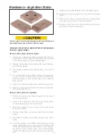
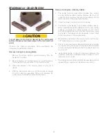
Remove and replace moving blade:
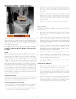
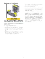
1. Remove or swing the Coper Notcher guard assembly up
and away from the Coper Notcher table.
2. Remove the two 1/2" socket head cap screws that se-
cure the existing top Coper Notcher blade to the moving
center.
3. Clean the keyway in the moving center of any dirt or de-
bris.
4. Install the top Coper Notcher blade with the keyway up
and the “foot” of the blade facing the center of the ma-
chine. Secure the top blade using two 1/2" socket head
cap screws. Tighten bolts.
Remove and replace stationary blades:
1 Loosen the set screws (if provided) located at the sides
of the Coper Notcher table.
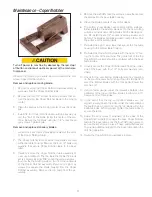
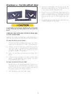
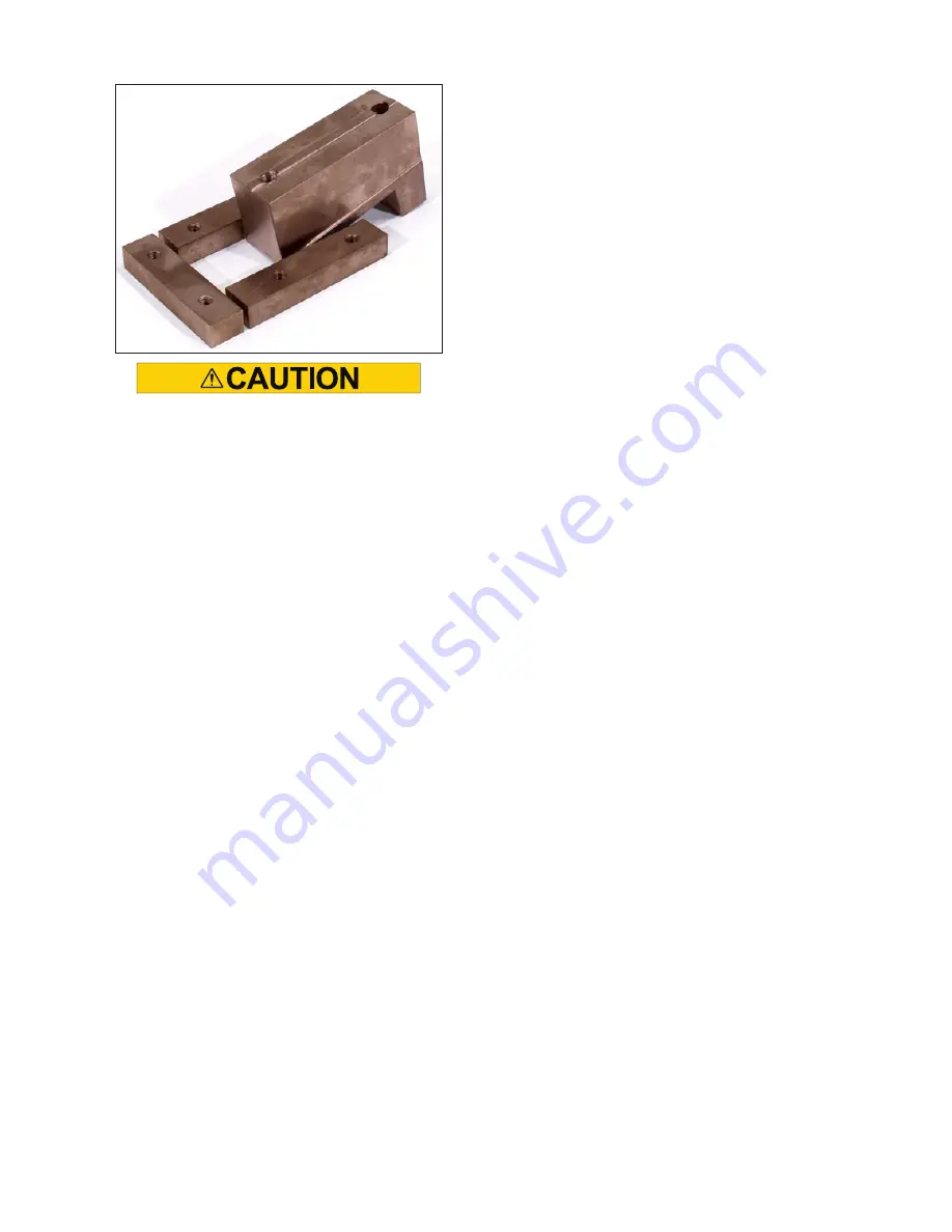
2. The Coper Notcher table includes three blades secured
within the table housing. Remove the four 1/2" bolts and
washers that secure Coper Notcher table to the base
table.
3. Carefully remove the Coper Notcher table assembly to
a secure workbench. The top table that holds the blade
set is secured by eight 3/8" socket head cap screws -
four from the top working surface, four from the underside
of the Coper Notcher assembly. Remove all eight cap
screws to separate the blade housing from the Coper
Notcher assembly. Remove the top table from the as-
sembly.
4. Remove the six 3/8" socket head cap screws that secure
the blades into the base table housing.
5. Clean the blade pockets of any dirt or debris.
6. The bottom shear blades have multiple cutting surfaces.
Either rotate/flip the existing blade set to the new cutting
surfaces or install new cutting blades into the blade pock-
ets. Re-install the six 1/2" socket head cap screws and
tighten. The blades should be parallel to each other at the
top surface of the working table.
7. Re-install the eight cap screws that secure the top table
housing to the bottom table housing.
8. Re-install the Coper Notcher table with the open “U” fac-
ing the center of the machine. The guide foot of the top
Coper Notcher blade should be centered within the base
table blades.
9. Loosely secure the Coper Notcher table from the under-
side of the base with four 1/2" bolts and washers (pro-
vided).
10. Check for top and bottom blade alignment by powering
up the machine and slowly inching down the top blade to
meet the bottom blades with the foot pedal. Power the
machine off.
11. Using a feeler gauge, adjust the clearance between the
perimeter of the top and bottom blades to allow for .010"
clearance on all three sides.
12. In the event that the top and bottom blades are not
aligned, simply loosen the bolts under the table allowing
the table to be moved to center the top blade within the
bottom blades. When aligned, tighten the table bolts to
secure the table.
13. Adjust the set screws (if provided) at the sides of the
Coper Notcher table to engage the base Coper Notcher
table to the base table. Lock the four 3/8" nuts in place to
secure the set screws in place. These added fixtures are
to provide additional support to the base table during the
notching operation.
14. Swing the Coper Notcher guard back in place.
Maintenance - Coper Notcher
Summary of Contents for 55 Ton
Page 2: ......
Page 41: ...37 55 Ton Exploded View ...
Page 42: ...38 55 Ton Parts List ...
Page 44: ...40 www clevelandsteeltool com 474 E 105th St Cleveland OH 44108 800 446 4402 ...

