background image

Part Lists

A - 4 Bottom (D470V)

A.Part Lists

Bottom (D470V)

Figure 2

Bottom (D470V)

(長卡時不使用)

無鉛

無鉛

無鉛

Summary of Contents for D470V

Page 1: ......

Page 2: ......

Page 3: ...Preface I Preface Notebook Computer D470V D480V Service Manual ...

Page 4: ...r in part be reproduced translated transmitted or reduced to any machine readable form without prior consent from the vendor manufacturer or creators of this publica tion except for copies kept by the user for backup purposes Brand and product names mentioned in this publication may or may not be copyrights and or registered trademarks of their respective companies They are mentioned for identific...

Page 5: ... information for servicing and or upgrading components of the D470V D480V series notebook PC The following information is included Chapter 1 Introduction provides general information about the location of system elements and their specifications Chapter 2 Disassembly provides step by step instructions for disassembling parts and subsystems and how to upgrade elements of the system Appendix A Part ...

Page 6: ...ng an electrical storm There may be a remote risk of elec trical shock from lightning 3 Do not use the telephone to report a gas leak in the vicinity of the leak 4 Use only the power cord and batteries indicated in this manual Do not dispose of batteries in a fire They may explode Check with local codes for possible special disposal instructions 5 This product is intended to be supplied by a Liste...

Page 7: ... down properly and don t forget to save your work Remember to periodically save your data as data may be lost if the battery is depleted Do not expose the computer to any shock or vibration Do not place it on an unstable surface Do not place anything heavy on the computer Do not expose it to excessive heat or direct sunlight Do not leave it in a place where foreign matter or mois ture may affect t...

Page 8: ... its purpose If you do not have access to a compatible outlet have a qualified electrician install one When you want to unplug the power cord be sure to disconnect it by the plug head not by its wire Make sure the socket and any extension cord s you use can support the total current load of all the connected devices Before cleaning the computer make sure it is disconnected from any external power ...

Page 9: ...led or discarded Keep the battery away from metal appliances Affix tape to the battery contacts before disposing of the battery Do not touch the battery contacts with your hands or metal objects Battery Disposal The product that you have purchased contains a rechargeable battery The battery is recyclable At the end of its useful life under various state and local laws it may be illegal to dispose ...

Page 10: ...ng manual for additional information User s Manual on CD This describes the notebook PC s features and the procedures for operating the computer and its ROM based setup pro gram It also describes the installation and operation of the utility programs provided with the notebook PC ...

Page 11: ...arts 1 10 Mainboard Overview Top Connectors 1 11 Mainboard Overview Bottom Connectors 1 12 Disassembly 2 1 Overview 2 1 Maintenance Tools 2 2 Connections 2 2 Maintenance Precautions 2 3 Cleaning 2 3 Disassembly Steps 2 4 Removing the Battery 2 8 Removing the Sub Woofer 2 9 Removing the Hard Disk Drive Assembly 2 10 Hard Disk Upgrade Process 2 10 Removing the System Memory RAM 2 11 Memory Upgrade P...

Page 12: ...ppy Disk Drive D480W A 25 Hard Disk Drive D480W A 26 Schematic Diagrams B 1 System Block Diagram B 2 Socket 478 1 of 2 B 3 Socket 478 ITP 2 of 2 B 4 Clock Generator B 5 M650 Host AGP 1 of 4 B 6 M650 Memory for DDR 2 of 4 B 7 M650 CRT Out 3 of 4 B 8 M650 Power 4 of 4 B 9 DDR Memory DIMM B 10 DDR SSTL 2 Termination B 11 LVDS Interface SiS302LV B 12 Panel Con LED Indicator B 13 962 PCI IDE HyperZip 1...

Page 13: ...face XI Preface VGA DRAM 1 of 2 Termination B 34 VGA DRAM 2 of 2 B 35 Mobility M9 P POW B 36 VCORE B 37 DDR Power B 38 System Power B 39 Charger B 40 SW Board and HotKey B 41 TouchPad and Switch Board B 42 ...

Page 14: ...Preface XII Preface ...

Page 15: ...perating systems e g DOS Windows 9x Windows NT 4 0 Windows 2000 Windows XP OS 2 Warp UNIX etc have their own manuals as do application software e g word processing and database programs If you have questions about those programs you should consult those manuals The D470V D480V series notebook is designed to be upgradeable See Disassembly on page 2 1 for a detailed de scription of the upgrade proce...

Page 16: ...up to 1024 MB 128 256 512MB DDR Modules BIOS One 512KB Flash ROM Phoenix BIOS LCD Options 17 0 WXGA TFT 1440x900 Display ATI Mobility Radeon 9600 PRO M10 Ultra AGP 8X 2D 3D graphics engine Advanced HW accelerator for DVD playback Fully DirectX 9 compliant notebook GPU 128 bit memory interface External memory 128MB DDR SGRAM On Board Dual view display monitor Device Bay Options Bay One Fixed 6 in 1...

Page 17: ...jack for LAN One DC in jack One S PDIF out port 3 Built in hot key buttons WWW E Mail application One S Video jack for video input option with TV Tuner module One Line in jack for audio input option with TV Tuner module Communication 56K Plug Play modem V 90 V 92 Compliant Infrared transfer 115 2K bps SIR 4M bps FIR IrDA 1 1 compliant 802 11b wireless LAN module option PC Camera module factory opt...

Page 18: ... 90 Physical Dimensions 393 w x 275 d x 37 5 h mm Weight Around 3 85 kg depend on optional modules included without battery Optional DVD ROM Drive module DVD ROM CD RW Combo Drive module CD RW Drive module DVD RW Drive module Software DVD Player Wireless LAN module Bluetooth module PC Camera module Sub Woofer Module TV Tuner module Feature Specification ...

Page 19: ...Top View Figure 1 Top View 1 Optional PC Camera 2 LCD 3 Built In Microphone 4 LED Power Communication Indicators 5 LED Status Indicators 6 Hot Key buttons 7 Close Cover Lid Switch 8 Power Button 9 Keyboard 10 TouchPad and Buttons 11 Built In Speakers 2 6 4 5 7 1 8 3 9 10 11 11 ...

Page 20: ...rared Transceiver functions with optional TV Tuner 3 Mini IEEE 1394 Port 4 S P DIF Out Port 5 Microphone In Jack 6 Headphone Out Jack 7 Infrared Transceiver 8 Wireless Bluetooth Device ON OFF Switch 9 Built In Speakers 4 5 6 8 1 2 1 3 9 9 7 Figure 3 Left Side View 1 CD Device Bay 2 Card Reader 3 PC Card PCMCIA Slot 4 PC Card PCMCIA Slot Eject Buttons 3 1 4 2 ...

Page 21: ...or Right Side Rear Views 1 Figure 4 Right Side View 1 Security Lock Slot Figure 5 Rear View 1 Vent 2 DC In Jack 3 2 USB 2 0 1 1 Ports 4 External Monitor CRT Port 5 Parallel Port 6 Serial Port 7 S Video Out Port 8 PS 2 Type Port 9 RJ 11 Phone Jack 10 RJ 45 LAN Jack 3 4 5 6 7 8 9 10 1 2 1 ...

Page 22: ... 6 Bottom View 1 Vent Fan Intake 2 Battery Cover 3 Hard Disk Cover 4 Bluetooth Module Cover 5 CPU Memory Socket Cover 6 Optional Module Cover Sub Woofer or TV Tuner or 6 in 1 Flash Card Reader Note The RAM and optional Wireless LAN module are lo cated under the CPU Heatsink Cover 1 1 2 4 5 3 6 1 1 ...

Page 23: ... Introduction Mainboard Overview Top Key Parts Figure 7 Mainboard Top Key Parts 1 PC Card Assembly 2 Northbridge SiS 648FX 839 mBGA 3 Southbridge SiS 963 371 mBGA 4 LAN Realtek RTL8100C RTL 8110S 5 VGA Chipset ATI Mobility M10 6 Video RAM 1 2 3 4 5 6 6 ...

Page 24: ...iew Bottom Key Parts Figure 8 Mainboard Bottom Key Parts 1 CPU Socket no CPU installed 2 Memory Slots no memory installed 3 CardBus ENE 1410 4 ALC650 Audio Codec 5 LPC H8 6 LPC Super I O NS PC87393 7 Clock Generator 8 Clock Buffer 9 Flash ROM 10 1394 PHY TSB41LV01 1 2 3 4 5 6 8 7 9 10 ...

Page 25: ...or CN1 2 LCD and Inverter Connector JLCD1 3 Video Camera Cable Connector JCCD1 4 Power Switch Board Cable Connector JSW1 5 TouchPad Cable Connector JTP1 6 Keyboard Cable Connector JKB1 7 Modem Module Connector JMDC1 8 Speaker Cable Connector JSPK1 6 9 Card Reader Connector JCR1 10 Fan Cable JFAN2 11 TV Tuner Connector JTV1 5 7 8 4 6 1 2 3 9 8 10 8 8 8 8 11 ...

Page 26: ...m Connectors Figure 10 Mainboard Bottom Connectors 1 Wireless LAN Connector JWL1 2 DDR Fan Cable Connector JFAN3 3 CD ROM Device Connector JCDROM1 4 Hard Disk Cable Connector JHDD1 5 Bluetooth Module Connector JBT1 6 CMOS Battery Cable Connector JBAT1 7 Battery Cable Connector CN5 1 2 3 4 5 6 7 ...

Page 27: ...mbly process easier each section may have a box in the page margin Information contained under the figure will give a synopsis of the sequence of procedures involved in the disassembly procedure A box with a lists the relevant parts you will have after the disassembly process is complete Note The parts listed will be for the dis assembly procedure listed ONLY and not any previous disassembly step ...

Page 28: ...acing the connection make sure the connector is oriented in the same way The pin1 side is usually not indicated Pressure sockets for multi wire connectors To release this connector type grasp it at its head and gently rock it from side to side as you pull it out Do not pull on the wires themselves When replacing the connection do not try to force it The socket only fits one way Pressure sockets fo...

Page 29: ... Do not pull on the wire 6 Peripherals Turn off and detach any peripherals 7 Beware of static discharge ICs such as the CPU and main support chips are vulnerable to static electricity Before handling any part in the computer discharge any static electricity inside the computer When handling a printed circuit board do not use gloves or other materials which allow static electricity buildup We sugge...

Page 30: ... remove the Bluetooth Module 1 Remove the battery page 2 8 2 Remove the Bluetooth module page 2 14 To remove the Wireless LAN Module 1 Remove the battery page 2 8 2 Remove the Wireless LAN module page 2 15 To remove the Processor 1 Remove the battery page 2 8 2 Remove the processor page 2 16 To remove the Keyboard Center Cover 1 Remove the battery page 2 8 2 Remove the keyboard center cover page 2...

Page 31: ...2 18 9 Remove the LCD assembly page 2 19 10 Remove the top case module page 2 21 11 Remove the TouchPad page 2 22 To remove the LED board 1 Remove the battery page 2 8 2 Remove the HDD page 2 9 3 Remove the system memory page 2 10 4 Remove the CD device page 2 12 5 Remove the Bluetooth module page 2 14 6 Remove the Wireless LAN module page 2 15 7 Remove the processor page 2 16 8 Remove the keyboar...

Page 32: ... 21 11 Remove the modem page 2 24 12 Remove the mainboard page 2 25 13 Remove the sub woofer page 2 26 To remove the Card Reader 1 Remove the battery page 2 8 2 Remove the HDD page 2 9 3 Remove the system memory page 2 10 4 Remove the CD Device page 2 12 5 Remove the Bluetooth module page 2 14 6 Remove the Wireless LAN module page 2 15 7 Remove the processor page 2 16 8 Remove the keyboard center ...

Page 33: ...emove the inverter page 2 29 12 Remove the LCD panel page 2 30 To remove the Camera Module 1 Remove the battery page 2 8 2 Remove the HDD page 2 9 3 Remove the system memory page 2 10 4 Remove the CD device page 2 12 5 Remove the Bluetooth module page 2 14 6 Remove the Wireless LAN module page 2 15 7 Remove the processor page 2 16 8 Remove the keyboard center cover page 2 18 9 Remove the LCD assem...

Page 34: ...ver 3 Carefully use a small screwdriver disconnect the battery cable at point 4 Lift the battery out of the computer 5 When replacing the battery connect the cable first 4 Battery Cover 6 Battery 3 Screws 1 3 4 5 6 2 5 a 6 4 b 1 3 c Figure 1 Battery Removal a Remove the 3 screws and the battery cover b Carefully disconnect the battery cable c Remove the battery ...

Page 35: ...er 3 Carefully disconnect the cable at point 4 Lift the HDD assembly out of the computer remove the hard disk from case and disconnect the cable 5 Reverse the process to install a new hard disk Figure 2 HDD Assembly Assembly Removal a Remove the 4 screws b Disconnect the HDD ca ble c Lift the HDD assembly out of the bay 1 4 5 6 7 5 Hard Disk Cover 7 Hard Disk 4 Screws 1 2 3 4 6 HDD System Warning ...

Page 36: ... 8 2 Remove screws from the memory socket cover 3 Carefully lift up the memory socket cover a fan cable is still attached to the mainboard and you can discon nect it 4 If there is a module currently installed which needs to be upgraded replaced then remove it Heat Sink Unit Before you undertake any upgrade proce dures make sure that you have turned off the power and discon nected all peripherals a...

Page 37: ... the slot as it will go DO NOT FORCE IT it should fit without much pressure 10 Press the module down towards the mainboard until the slot levers click into place to secure the module 11 Replace the memory socket cover be careful with the fan cable and the 8 screws see page 2 10 12 Restart the computer 13 The BIOS will register the new memory configuration as it starts up 1 2 1 2 3 a Figure 4 Remov...

Page 38: ...ge 2 8 2 Remove screws from the memory socket cover 3 Carefully lift up the memory socket cover a fan cable is still attached to the mainboard and you can discon nect it 1 8 9 10 Figure 5 Memory Socket Cover Removal a Remove the screws b Carefully lift the cover off the computer a 9 b 8 1 5 4 3 6 7 2 10 9 Socket Cover 8 Screws ...

Page 39: ...and carefully slide it into the computer the device only fits one way DO NOT FORCE IT The screw holes should line up 6 Replace the memory socket cover be careful with the fan cable and the 8 screws 7 Restart the computer to allow it to automatically detect the new device 1 2 2 1 Figure 6 CD Device Removal Push the CD device out off the computer at point 2 1 CD Device ...

Page 40: ...ully lift up the Bluetooth module cover off the computer 4 Remove screws and carefully disconnect cables then remove the Bluetooth module 1 2 3 Figure 7 Bluetooth Module Removal a Remove the screws b Carefully lift the cover off the computer c Remove the screws and disconnect the cables d Remove the Bluetooth module 4 7 8 9 10 1 2 9 6 4 8 a 3 b c d 10 5 7 3 Bluetooth Cover 10 Bluetooth Module 6 Sc...

Page 41: ...ove screws and carefully disconnect cables 5 Lift the Wireless LAN module off the computer 1 8 9 10 Figure 8 Wireless LAN Module Removal a Remove the screws b Carefully lift the cover off the computer c Remove the screws and disconnect the cables d Remove the WLAN module 11 12 13 14 15 Antenna Cable Connection When re inserting a Wireless LAN module make sure the antenna cable connects to the conn...

Page 42: ...the heat sink off the computer 1 7 9 10 11 14 15 Figure 9 Processor Removal a Remove the screws b Carefully lift the cover off the computer c Remove the screws in the order indicated d Remove the heat sink Heat Sink Unit The elongated heat sink pictured ap plies to models in this series with two CPU fan units Some mod els may have a shorter heat sink unit and a single CPU fan 15 9 Socket Cover 15 ...

Page 43: ...computer 1 2 3 4 5 Figure 10 Processor Removal cont d a Remove the screws and lift the CPU holder off the computer b Raise the lever to unlock the CPU c Lift the CPU off the sock et 1 a 5 b c Caution The heat sink and CPU area in general contains parts which are subject to high temperatures Allow the area time to cool before removing these parts 5 4 2 3 3 3 CPU Holder 5 CPU ...

Page 44: ...not to bend the key board ribbon cable 4 Set the keyboard aside and remove screws from the keyboard shielding plate and lift off the shielding plate 5 Remove the center cover 1 4 5 6 7 18 19 20 Figure 11 Keyboard Center Cover Removal a Press in the keyboard latches and elevate the keyboard b Disconnect the keyboard cable c Lift the keyboard up and out of the computer d Remove the screws from shiel...

Page 45: ...th module page 2 14 WLAN module page 2 15 processor page 2 16 and the key board and center cover page 2 18 2 Remove screws from the bottom of the computer 3 Remove screws from the rear of the computer 1 13 14 17 Figure 12 LCD Assembly Removal a Remove the screws from the bottom of the compu ter b Remove the screws from the rear of the computer 17 Screws a 11 13 10 8 1 5 4 6 7 2 b 12 2 9 14 16 17 ...

Page 46: ... 3 4 Figure 13 LCD Assembly Removal cont d a Remove the hinge cov ers b Disconnect the cables c Lift the LCD assembly up off the computer be careful with the WLAN and Bluetooth cables 2 a 1 b c 4 3 1 1 5 CPU Fan Units The twin fan units pic tured apply to mod els in this series with an elongated heat sink Some models may have a shorter heat sink unit and a single CPU fan 6 6 6 1 Hinge Covers 3 4 L...

Page 47: ... 14 WLAN module page 2 15 processor page 2 16 keyboard and center cover page 2 18 and LCD assembly page 2 19 2 Release the connectors and remove screws 3 Carefully lift the top case module off the bottom case 1 4 5 8 Figure 14 Top Case Module Removal a Remove the screws and release the connectors b Carefully lift the top case module off the bottom case 10 Bottom Case 9 Top Case 4 Screws a 1 4 2 b ...

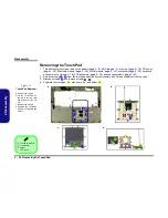
Page 48: ...op case module page 2 21 2 Remove screws from the touchpad and click board assembly and lift the assembly off the top case 3 Disconnect cable and remove screws 4 Separate the touchpad click board and holder 1 8 9 10 11 12 13 Figure 15 TouchPad Removal a Remove the screws b Lift the TouchPad as sembly of the top case and disconnect the ca ble c Remove the screws d Separate the TouchPad module Click...

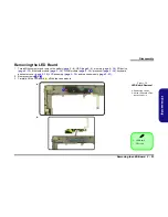
Page 49: ...ce page 2 12 Bluetooth module page 2 14 WLAN module page 2 15 processor page 2 16 keyboard and center cover page 2 18 LCD assembly page 2 19 and top case module page 2 21 2 Remove screws 3 Carefully lift the LED board off the top case module 1 2 3 Figure 16 LED Board Removal a Remove the screws b Lift the LED board off the top case module 3 LED Board 2 Screws a 1 2 b 3 ...

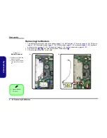
Page 50: ...age 2 14 WLAN module page 2 15 processor page 2 16 keyboard and center cover page 2 18 LCD assembly page 2 19 and top case module page 2 21 2 Remove screws and release the modem cable at point 3 Lift up the modem module and cable 1 2 3 4 Figure 17 Modem Removal a Remove the screws and release the cable b Lift the modem module and cable off the compu ter 4 Modem Module 2 Screws a 11 1 2 b 3 4 ...

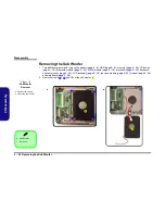
Page 51: ...ge 2 15 processor page 2 16 keyboard and center cover page 2 18 LCD assembly page 2 19 top case module page 2 21 and modem page 2 24 2 Release the connectors and remove screw 3 Carefully lift the mainboard off the bottom case 1 8 9 10 Figure 18 Mainboard Removal a Disconnect the cables and remove the screw b Carefully lift the main board off the bottom case 9 Mainboard 10 Bottom Case 1 Screw a 9 1...

Page 52: ...vice page 2 12 Bluetooth module page 2 14 WLAN module page 2 15 processor page 2 16 keyboard and center cover page 2 18 LCD assembly page 2 19 top case module page 2 21 modem page 2 24 and mainboard page 2 25 2 Remove screws and lift out the sub woofer 1 4 5 Figure 19 Sub Woofer Removal a Remove the screws b Lift out the sub woofer 5 Sub Woofer 4 Screws a 4 3 b 5 5 1 2 ...

Page 53: ... CD device page 2 12 Bluetooth module page 2 14 WLAN module page 2 15 processor page 2 16 keyboard and center cover page 2 18 LCD assembly page 2 19 top case module page 2 21 modem page 2 24 and mainboard page 2 25 2 Remove screws and lift out the card reader 1 2 3 Figure 20 Card Reader Assembly Removal a Remove the screws b Lift out the card reader 3 Card Reader 2 Screws a 1 2 b 3 3 ...

Page 54: ... 2 14 WLAN module page 2 15 processor page 2 16 keyboard and center cover page 2 18 LCD assembly page 2 19 top case module page 2 21 modem page 2 24 and mainboard page 2 25 2 Carefully push the pins on the PCMCIA module as indicated 3 Remove the PCMCIA module from the mainboard 1 2 3 Figure 21 PCMCIA Module Removal a Push the pins to release the PCMICA module b Remove the PCMCIA module 3 PCMCIA Mo...

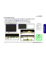
Page 55: ...ubber covers from the front of the LCD assembly 3 Run your finger around the middle of the frame to carefully unsnap the LCD front panel module 4 Remove screw from the inverter then turn over the inverter and disconnect cables 5 Lift the inverter up off the LCD assembly 1 6 7 8 Figure 22 Inverter Removal a Remove the screws b Remove the front panel module c Remove the screw on the inverter d Turn ...

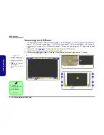
Page 56: ...module page 2 21 and inverter page 2 29 2 Remove the screws and hinges from the front of the LCD assembly 3 Lift the LCD panel out from the rear panel module 4 Remove screws from the LCD brackets then separate the brackets from the LCD panel Figure 23 LCD Panel Removal a Remove the screws and hinges b Separate the LCD and the rear panel c Remove the LCD brack ets 1 8 9 11 10 12 19 9 Hinges 2 10 Re...

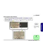
Page 57: ...ge 2 15 processor page 2 16 keyboard and center cover page 2 18 LCD assembly page 2 19 top case module page 2 21 inverter page 2 29 and LCD panel page 2 30 2 If the camera cable is taped down e g as in Figure 24 at point lift the tape up to release the cable then care fully remove the camera module 2 Camera Module Figure 24 Camera Module Removal a Release the camera ca ble if it is taped down b Re...

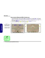
Page 58: ...2 15 processor page 2 16 keyboard and center cover page 2 18 LCD assembly page 2 19 top case module page 2 21 inverter page 2 29 and LCD panel page 2 30 2 Remove screws for the Bluetooth antenna and or screws for WLAN antenna 3 Remove the Bluetooth antenna and or WLAN antenna Figure 25 Bluetooth WLAN Antenna Removal a Remove the screws for the appropriate antenna b Remove the antenna s 1 2 3 4 5 6...

Page 59: ... numbers Your organization may use a different system so be sure to cross check any relevant documentation Note Some assemblies may have parts in common especially screws However the part lists DO NOT indicate the total number of duplicated parts used Note Be sure to check any update notices The parts shown in these illustrations are appropriate for the system at the time of publication Over the p...

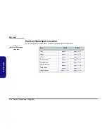
Page 60: ... the appropriate part list illustration Table 1 1 Part List Illustration Location Part D470V D480V Top page A 3 page A 11 Bottom page A 4 page A 12 LCD 17 page A 5 page A 13 CD ROM Drive page A 6 page A 14 CD RW Drive page A 7 page A 15 DVD ROM Drive page A 8 page A 16 Combo Drive page A 9 page A 17 Hard Disk Drive page A 10 page A 18 ...

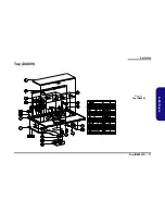
Page 61: ...Part Lists Top D470V A 3 A Part Lists Top D470V Figure 1 Top D470V ...

Page 62: ...Part Lists A 4 Bottom D470V A Part Lists Bottom D470V Figure 2 Bottom D470V 長卡時不使用 無鉛 無鉛 無鉛 ...

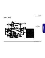
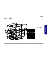
Page 63: ...Part Lists LCD 17 D470V A 5 A Part Lists LCD 17 D470V Figure 3 LCD 17 D470V ...

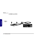
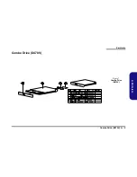
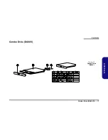
Page 64: ...Part Lists A 6 CD ROM Drive D470V A Part Lists CD ROM Drive D470V Figure 4 CD ROM Drive D470V ...

Page 65: ...Part Lists CD RW Drive D470V A 7 A Part Lists CD RW Drive D470V Figure 5 CD RW Drive D470V ...

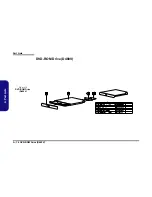
Page 66: ...Part Lists A 8 DVD ROM Drive D470V A Part Lists DVD ROM Drive D470V Figure 6 DVD ROM Drive D470V ...

Page 67: ...Part Lists Combo Drive D470V A 9 A Part Lists Combo Drive D470V Figure 7 Combo Drive D470V ...

Page 68: ...Part Lists A 10 Hard Disk Drive D470V A Part Lists Hard Disk Drive D470V Figure 8 HDD Drive D470V ...

Page 69: ...Part Lists Top D480V A 11 A Part Lists Top D480V Figure 9 Top D480V ...

Page 70: ...Part Lists A 12 Bottom D480V A Part Lists Bottom D480V Figure 10 Bottom D480V 長卡時不使用 無鉛 無鉛 無鉛 ...

Page 71: ...Part Lists LCD 17 D480V A 13 A Part Lists LCD 17 D480V Figure 11 LCD 17 D480V ...

Page 72: ...Part Lists A 14 CD ROM Drive D480V A Part Lists CD ROM Drive D480V Figure 12 CD ROM Drive D480V ...

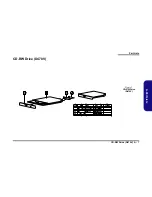
Page 73: ...Part Lists CD RW Drive D480V A 15 A Part Lists CD RW Drive D480V Figure 13 CD RW Drive D480V ...

Page 74: ...Part Lists A 16 DVD ROM Drive D480V A Part Lists DVD ROM Drive D480V Figure 14 DVD ROM Drive D480V ...

Page 75: ...Part Lists Combo Drive D480V A 17 A Part Lists Combo Drive D480V Figure 15 Combo Drive D480V ...

Page 76: ...Part Lists A 18 Hard Disk Drive D480V A Part Lists Hard Disk Drive D480V Figure 16 HDD Drive D480V ...

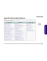
Page 77: ...ory for DDR 2 of 4 Page B 7 LPT COM Port Page B 24 Charger Page B 41 M648FX 3 CRT Out 3 of 4 Page B 8 LPC H8 Page B 25 S W Board Hot Key Page B 42 M648FX 4 Power 4 of 4 Page B 9 LAN RTL8100S B 32 RTL8100C Page B 26 TouchPad SwitchBoard Page B 43 DDR Memory DIMM Page B 10 Audio Codec ALC650 Page B 27 DDR SSTL 2 Termination Page B 11 Audio Out Off Board Connectors Page B 28 LVDS Interface SiS302LV P...

Page 78: ...G TV OUT SOCKET 478 SiS 302LV ATI M10P SiS 648FX PANEL KBC H8 FDD CON EXT PS2 Ultra 66 100 133 TV Tuner AGP Bus 66MHz Host Bus AC 97 I F ALC650 371 mBGA RTL 8110S INT KB Card Reader MDC CRT PORT 1394 PHY DDR INTERFACE USB PORT B BLUE BOOTH IR EXT KB H8S 2149 HM LPC Super I O ENE 1410 PANEL M I I NS PC87393 HDD CD ROM CON 839 mBGA TOUCH PAD CLOCK I F PRESCOTT LPC I F CardBus XBUS Rtt VGA SiS 963 Re...

Page 79: ...AA20 J26 K25 K26 L25 AE1 AE2 AE3 AE4 AE5 AA2 A10 A12 A14 A16 A18 A20 A8 AA10 AA12 AA14 AA16 AA18 AA8 AB11 AB13 AB15 AB17 AB19 AB7 AB9 AC10 AC12 AC14 AC16 AC18 AC8 AD11 AD13 AD15 AD17 AD19 AD7 AD9 AE10 AE12 AE14 AE16 AE18 AE20 AE6 AE8 AF11 AF13 AF15 AF17 AF19 AF2 AF21 AF5 AF7 AF9 B11 B13 B15 B17 B19 B7 B9 C10 C12 C14 C16 C18 C20 C8 D11 D13 D15 D17 D19 D7 D9 E10 E12 E14 E16 E18 E20 E8 F11 F13 F15 F1...

Page 80: ...R306 150 R425 56_1 T C493 0 1UF 1 2 R13 51 1_1 R400 49 9_1 R350 51 R103 75 C336 220P R71 56_1 R95 56_1 C376 10U 0805 R73 62_1 C405 220P L99 4 7uH_SMD_30 1 2 T R81 27 R305 51_1 R290 1 5K T T R304 56_1 R403 10K U20 EN1617 15 12 14 6 10 1 5 9 13 16 2 3 4 11 7 8 STBY SMBDATA SMBCLK ADD1 ADD0 NC CRIT1 NC CRIT0 NC OS NC NC VCC DXP DXN ALERT GND GND R371 10K R93 51_1 JCPU1B NORTHWOOD478 AC1 V5 A5 AC26 AD...

Page 81: ...5 0 1UF R451 22 R91 22 R415 22 C215 10U 0805 R414 22 L30 FCM2012V121 1 2 C220 10U 0805 C600 10PF R RP65 4P2R 0 1 2 3 4 L142 FCM1608K121 1 2 R523 22 R437 10K RP49 4P2R 0 1 2 3 4 C219 0 1UF R464 4 7K R C87 10PF R RP66 4P2R 0 1 2 3 4 C602 10PF R R449 33 C736 0 01UF C505 0 1UF C122 10PF R R92 10K C737 0 1UF U21 CLOCK GEN 660 1 3 2 6 7 14 16 17 20 21 22 30 31 27 26 34 35 44 40 36 37 47 39 43 23 4 9 10 ...

Page 82: ... 20MIL WBF 30 HD 11 AC BE 0 3 BREQ0 3 AD_STB 0 1 30 AFRAME N16 AAD31 BVSYNC 30 HA 18 HD 31 AAD22 C379 0 01UF APAR 30 C4XAVDD SBA6 HD 29 HD 6 DBI 3 HREQ 2 ASERR AAD9 ATRDY 30 C451 0 1UF VTT DBI 2 R373 22 R 20MIL HA 21 HD 36 DBI 0 3 3 AAD 19 26 10 30 HA 24 R408 50_1 ST 0 2 30 HDSTBN 2 HD 42 C341 0 01UF R295 75_1 DBI_HI 30 HTRDY HASTB 0 HD 52 VBCLK 10 HA 4 HCLK 661 AAD20 AD_STB 0 1 R41 22 R HOST ASTO...

Page 83: ...AMTEST DLLAVDD DLLAVSS DDRAVDD DDRAVSS TRAP2 DDRCOMP_P DDRCOMP_N DDRVREFA DDRVREFB R138 0 3VS MD41 DQS2 CKE 0 5 7 RCS 0 RDQS0 MD50 RMD51 RP13 8P4R 10 1 8 2 7 3 6 4 5 R472 150_1 FWDSDCLKO 4 MD14 RMD59 DQM0 MD44 DQS4 MD1 RP8 8P4R 0 8 1 7 2 6 5 3 4 RDQM7 MD32 RP46 8P4R 10 1 8 2 7 3 6 4 5 CS 4 MD10 DQS3 MA4 SRAS MD52 FWDSDCLKO MD3 MD63 3V RMD20 RMD27 RMD13 SCAS RMD50 MA14 L130 FCM1608K121 1 2 Rs place...

Page 84: ...E14 D12 E12 D11 B12 B13 A13 A11 B11 E13 C11 B14 C14 VOSCI INT A ZAD0 ZAD1 ZAD2 ZAD3 ZAD4 ZAD5 ZAD6 ZAD7 ZAD8 ZAD9 ZAD10 ZAD11 ZAD12 ZAD13 ZAD14 ZAD15 ZAD16 ZCLK ZUREQ ZDREQ ZSTB0 ZSTB0 ZSTB1 ZSTB1 ZVREF ZCOMP_N ZCOMP_P Z1XAVDD Z1XAVSS Z4XAVDD Z4XAVSS PCIRST PWROK AUXOK TRAP1 TRAP0 TESTMODE2 TESTMODE1 TESTMODE0 DLLEN ENTEST DCLKAVDD DCLKAVSS DACAVDD2 DACAVSS2 DACAVDD1 DACAVSS1 VCOMP VRSET VVBWN CSY...

Page 85: ...E30 E32 E36 F34 G32 G36 H34 J32 J36 K34 L32 L36 M34 N32 N36 P34 R32 T34 U32 U36 V34 W32 W36 Y34 AA32 AA36 AB34 AM10 AM12 AM14 AM16 AM18 AM20 AM22 AM24 AM26 AM28 AM30 AP9 AP11 AP13 AP15 AP17 AP19 AP21 AP23 AP25 AP27 AP29 AP31 AP33 AP35 AT8 AT10 AT12 AT16 AT18 AT20 AT22 AT24 AT26 AT28 AT30 AT32 AT34 AL32 AC32 AC36 AD34 AE32 AE36 AF34 AG32 AG36 AH34 AJ32 Y14 Y15 Y16 Y17 Y18 Y19 Y20 Y21 Y22 Y23 AA14 A...

Page 86: ...A0 A1 A2 A3 A4 A5 A6 A7 A8 A9 A10 AP A11 A12 BA0 BA1 DQ0 DQ1 DQ2 DQ3 DQ4 DQ5 DQ6 DQ7 DQ8 DQ9 DQ10 DQ11 DQ12 DQ13 DQ14 DQ15 DQ16 DQ17 DQ18 DQ19 DQ20 DQ21 DQ22 DQ23 DQ24 DQ25 DQ26 DQ27 DQ28 DQ29 DQ30 DQ31 DQ32 DQ33 DQ34 DQ35 DQ36 DQ37 DQ38 DQ39 DQ40 DQ41 DQ42 DQ43 DQ44 DQ45 DQ46 DQ47 DQ48 DQ49 DQ50 DQ51 DQ52 DQ53 DQ54 DQ55 DQ56 DQ57 DQ58 DQ59 DQ60 DQ61 DQ62 DQ63 VDD VDD VDD VDD VDD VDD VDD VDD VDD V...

Page 87: ...57 8P4R 33 8 1 7 2 6 5 3 4 RP61 8P4R 33 8 1 7 2 6 5 3 4 RP60 8P4R 33 8 1 7 2 6 5 3 4 RP59 8P4R 33 8 1 7 2 6 5 3 4 RP58 8P4R 33 8 1 7 2 6 5 3 4 RP56 8P4R 33 8 1 7 2 6 5 3 4 RP20 8P4R 33 8 1 7 2 6 5 3 4 R526 33 RP52 8P4R 33 8 1 7 2 6 5 3 4 RP19 8P4R 47 0402 8 1 7 2 6 5 3 4 RP27 8P4R 33 8 1 7 2 6 5 3 4 RP29 8P4R 33 8 1 7 2 6 5 3 4 RP24 8P4R 33 8 1 7 2 6 5 3 4 RP31 8P4R 33 8 1 7 2 6 5 3 4 RP23 8P4R 33...

Page 88: ...LPLL LAVSS LGND RESERVED LL2C RESERVED LL2C LAVDD LVDD RESERVED LDC7 RESERVED LDC7 LAVSS LGND RESERVED LDC6 RESERVED LDC6 LAVDD LVDD RESERVED LDC5 RESERVED LDC5 LVDSPLLVSS LGND RESERVED LDC4 RESERVED LDC4 LVDSPLLVDD LVDD LAVDD LVDD LX3P LDC3 LX3N LDC3 LAVSS LGND LXC1P LL1C LXC1N LL1C LAVDD LVDD LX2P LDC2 LX2N LDC2 LAVSS LGND LX1P LDC1 LX1N LDC1 LAVDD LVDD LX0P LDC0 LX0N LDC0 LAVSS LGND EXTSWING VS...

Page 89: ... LN TXCLK LP TXCLK UN TXOUT UP3 TXOUT UP1 TXOUT UP2 TXOUT UN3 TXOUT UN2 TXOUT UN1 TXOUT UP0 TXOUT UN0 CHA BATLOW LL2C ACIN_LED Z245 E MAIL WL_LED LEDPWR GATE_LID_SW LID_SW PANEL ENABKL ENAVDD C321 10PF L97 FCM2012V 121 Q28 2N7002 G S D C460 0 1UF Q30 2N7002 G S D L90 0 L101 0 C290 10PF L108 0 L85 0 C319 0 1UF L94 BK3216HS800 R59 10K L83 0 C350 0 1UF R287 10K D14 F01J2E A C JLCD1 CON50 1 3 5 7 9 11...

Page 90: ...2 IDESAB1 IDECS B1 IDECS B0 GNT1 ZAD16 C191 0 01UF R191 33 R477 56 C742 0 1UF R C148 0 1UF C699 0 1UF T C133 0 1UF T N19 C617 10UF 10V C149 0 1UF R478 56 R548 10K C743 0 1UF T RN43 8P4R 2 2K 8 1 7 2 6 5 3 4 C135 0 01UF R533 4 7K C616 10UF 10V N7 C147 0 01UF RP32 10P8R 2 7K 1 2 3 4 5 10 9 8 7 6 1 2 3 4 5 10 9 8 7 6 R476 150_1 R539 4 7K T L40 FCM1608K121 1 2 N8 R540 4 7K N9 RN44 8P4R 4 7K 8 1 7 2 6 ...

Page 91: ...163 0 R152 10K C717 0 1UF BGA5B 963 T18 P16 R17 R16 Y20 U18 T17 W20 V19 Y19 V18 W19 V5 T7 U6 W5 W4 U7 V6 C2 D2 D3 D1 C1 E4 B2 A1 A2 D5 W2 T5 D6 Y1 W3 G5 V3 A14 B14 D14 A3 A15 B1 E5 E13 A16 D13 B15 D4 F5 B3 E6 A8 A9 A6 B6 E8 D7 C6 B4 A7 C7 C8 D8 A5 B5 A4 B7 E9 C5 E7 B9 B8 V2 T8 T4 T6 W1 U5 U4 C4 C14 INIT A20M SMI INTR NMI IGNNE FERR STPCLK CPUSLP APICCK LDTREQ APICD0 THERM2 APICD1 GPIOFF LAD0 LAD1 ...

Page 92: ...7 6 5 CS SK DI DO VCC NC NC GND C152 0 1UF L38 FCM2012V121 1 2 L134 FCM2012V121 R 1 2 T R168 0 R C618 10UF 10V C669 10UF 10V L133 FCM2012V121 1 2 T T C156 20PF R502 10K T T T T T R135 10M C151 0 1UF SW1 SW DIP 4 1 2 3 4 8 7 6 5 R479 10K C621 10UF 10V T C626 0 1UF C654 0 1UF L132 FCM2012V121 R 1 2 JA3 SHORT A 1 2 R541 47K Y5 12MHz JA1 SHORT A 1 2 C619 10UF 10V R169 0 R BGA5C 963 V4 B18 C18 D18 D19 ...

Page 93: ...AUX OVDD_AUX OVDD_AUX OVDD_AUX PVDD_AUX PVDD_AUX VSSZ VDDZ VSSZ VSSZ VSSZ VSSZ VDDZ VSSZ VSSZ VDDZ VSS VSS VSS VSS VSS VSS VSS VSS VSS VSS VSS VSS VSS VSS VSS VSS VSS VSS VSS VSS VSS VSS VSS VSS VSS VSS VSS VSS VSS C650 10UF 10V R199 10K C667 0 1UF C661 10UF 10V C731 0 1UF D34 1SS355 A C C718 1UF C651 0 1UF C499 1UF C645 1UF C681 0 1UF R194 100 CT1 10uF_1206 C653 0 1UF C739 1UF Q39 MMBT3906 B E C ...

Page 94: ... B IDECS B1 IDESAB2 IDEIOW B IDECS B0 CD L IDEDB10 IDEDB7 IDEDB11 IDEDB3 IDEDB6 IDEDB4 IDERST IDESAB1 IDEDB5 IDEDB0 IDEDB12 IDEDB2 CSEL IDEIRQB CDGND IDESAB0 CD R HDDLED 1 IDEDB15 IDEDB8 IDEDB9 IDEDB1 WGATE 3MODE WRPRT DISKCHG INDEX HDSEL RDATA MTR0 STEP DRV0 WDATA IDEDA6 IDEDA7 IDEDA5 IDEDA1 IDEDA0 IDEDA8 IDEDA9 DIR TRK0 IDESAA2 IDEIOR B ICHRDYB IDE_LED IDEDB13 IDEDB14 IDEDB7 IDEREQB U4 TC7SZ08 2...

Page 95: ...eader CON R 1 2 3 4 C747 0 1UF C347 47P R L91 FCM1608K121 1 2 R246 0 C730 47PF R255 560K L50 FCM2012V121 1 2 R254 10K T JCCD1 CCD CON 1 2 3 4 L64 PLW3216S161SQ2 R 3 4 2 1 R731 0 R R730 0 R R569 0 R L139 FCM1608K121 1 2 L72 PLW3216S161SQ2 3 4 2 1 C216 10U 10V JUSB2 USB PLUG 5 6 7 8 1 2 3 4 9 10 V _OUT1 DATA_L1 DATA_H1 GND V _OUT2 DATA_L2 DATA_H2 GND GND GND C5 10UF 10V R527 100K C263 0 1UF C16 100U...

Page 96: ... 8 9 95 112 101 10 104 11 110 108 12 98 13 100 103 105 85 15 16 96 17 123 107 109 111 113 116 139 132 141 143 140 76 79 19 106 20 21 136 22 81 23 142 24 25 26 27 28 29 31 32 92 88 33 34 35 36 37 93 38 39 40 41 119 42 133 43 125 91 134 45 46 137 47 48 49 51 52 53 54 55 56 57 58 59 60 61 64 65 67 68 69 70 78 94 114 130 VCC VCCP SPKROUT VCCP VCC VS2 CVS2 VCC VPPD0 VPPD1 VCCD0 VCCD1 D10 CAD31 GRST D12...

Page 97: ... BE 1 C BE 2 FRAME AD7 AD12 B_CD1 B_CE1 B_WP B_OE B_CE2 B_CA14 B_CA19 B_CA20 B_CA21 B_INPACK B_RESET B_CA22 B_CA23 B_CD2 RN45 8P4R 43K 1 8 2 7 3 6 4 5 T T C777 0 1UF RP33 10P8R 43K 1 2 3 4 5 10 9 8 7 6 1 2 3 4 5 10 9 8 7 6 T T C757 0 1UF RN103 8P4R 43K 1 8 2 7 3 6 4 5 T U13 TPS2211 4 3 11 5 12 9 13 10 16 7 1 2 15 14 6 8 3 3V 3 3V BVCC 5V BVCC 12V BVCC BVPP SHDN GND VCCD0 VCCD1 VPPD0 VPPD1 5V OC RN...

Page 98: ...1 33 R676 1K R689 R C873 4 7U 0805 L146 BLM21P221SGPTM00 03 R C878 0 1UF C877 0 1UF C896 220P J4 1394_CON 4 3 2 1 6 5 TPA TPA TPB TPB GND GND C897 1UF C869 0 1UF T C871 10PF L61 FRC 1394 1 8 2 7 3 6 5 4 R707 56 2_1 R706 56 2_1 R705 56 2_1 R713 4 7K R704 56 2_1 R711 1K R703 1K C870 10PF R680 220 R710 1K T T R698 1K U38 TSB41AB1 17 18 63 64 32 33 57 58 39 48 49 50 25 26 61 62 30 31 42 51 52 56 40 41...

Page 99: ...P TRK0 WGATE WDATA SETP DIR DR0 MTR0 INDEX DENSEL DRATE0 IRSL2 PD0 INDEX PD1 TRK0 PD2 WP PD3 RDATA PD4 DSKCHG PD5 MSEN0 PD6 DRATE0 PD7 MSEN1 PNF XRDY SLCT WGATE PE WDATA BUSY_WAIT MTR1 ACK DR1 SLIN _ASTRB STEP INIT DIR ERR HDSEL AFD _DSTRB DENSEL STB _WRITE DCD1 DSR1 SIN1 RTS1 TEST SOUT1 XCNF0 CTS1 DTR1 _BOUT1 BADDR RI1 IRTX IRRX1 IRRX2_IRSL0 IRSL1 IRSL3 PWUREQ XD0 GPIO00 JOYABTN1 XD1 GPIO01 JOYBB...

Page 100: ... C307 0 1UF K D22 1SS355 A C C269 0 1UF K CP4 8P4C 180P 1 8 2 7 3 6 4 5 C2 180P CP1 8P4C 180P 1 8 2 7 3 6 4 5 CP5 8P4C 180P 1 8 2 7 3 6 4 5 CP6 8P4C 180P 1 8 2 7 3 6 4 5 JPRT1 PRT_PORT 13 25 12 24 11 23 10 22 9 21 8 20 7 19 6 18 5 17 4 16 3 15 2 14 1 28 29 RP1 10P8R 4 7K 1 2 3 4 5 10 9 8 7 6 1 2 3 4 5 10 9 8 7 6 R286 100K T U16 MAX3243 28 24 1 2 14 13 12 20 19 18 17 16 15 23 22 21 27 3 9 10 11 4 5...

Page 101: ... Y W C GND G VCC D4 JPS1 MS_K B 4 6 2 1 7 5 3 8 T R654 10K R616 4 7K R643 1M C303 0 1UF R651 0 0805 R C804 0 1UF R597 100 D21 F01J2E R C A C279 47P R650 0 0805 D20 F01J2E C A R653 10 R R712 100 0805 T C814 0 1UF F1 1 1A 1 2 R667 3 3K R 1SS355 D45 A C R625 22 R663 0 R622 0 J80DEBUG1 85205 5 R 1 3 5 7 9 2 4 6 8 10 C813 4 7U 0805 C282 47P D1 F1AJ3 A C C865 1UF L71 FCM2012V121 R695 10K R694 10K C866 0...

Page 102: ...AKE EECS VDD33 EEDO EEDI EESK GND LED3 LED2 LED1 LED0 GND HV HG LG2 CTRL18 LV2 XTAL1 XTAL2 RSET VSS ISOLATEB INTAB RSTB CLK GNTB REQB PMEB VSSPST VSSPST VSSPST VSSPST VSSPST VSSPST VSSPST VSSPST VDD18 VDD18 VDD18 VDD18 VDD18 VDD18 VDD18 VDD18 VDD18 C271 0 1U L113 BK2125HS121 2 1 R339 75 C427 0 01U R340 75 C411 10U 10V 0805 C428 0 1U R C298 0 1U C394 10U 10V 0805 L115 BK1608HS121 2 1 C354 10U 0805 ...

Page 103: ...857 0 22U D43 ISS355 A C R629 47 C826 1UF C887 4 7U 0805 R646 49 9K C818 0 01UF C795 0 01UF L46 FCM1608K 121 C790 1UF Q13 2N7002 G S D R671 1K C239 0 1UF C831 10UF 10V C784 1UF T C842 8200P R222 20K C793 0 01UF C828 0 1uF C234 1U R R218 100K R R686 10K R661 20K C886 0 1UF C817 0 01UF 1M R R630 C237 1UF C868 0 1UF C787 1UF R702 10K C849 1UF R 0 47U R C850 R648 4 7K C895 10UF 10V R669 15K R219 10K L...

Page 104: ...MIC39102 7 6 5 4 3 2 1 8 GND GND GND ADJ VOUT VIN EN GND R240 100K JTP1 CON4 1 2 3 4 R603 0 T C245 47U 16V 1 2 T T C243 10UF 10V R R550 100K C252 0 01UF U26 MIC39102 7 6 5 4 3 2 1 8 GND GND GND ADJ VOUT VIN EN GND C251 0 22U R C255 680P R243 1K R551 10K JAUDIO3 AUDIO_JACK 4 3 6 2 1 5 R242 1K C751 0 1UF R542 10K T R554 287K T T R593 10K R C250 0 1UF L57 FCM1608K 121 R238 1K JAUDIO1 AUDIO_JACK 4 3 6...

Page 105: ...3 MTH276D107 5 2 3 4 5 H20 C315D111 U10C 74LVC14 5 6 14 7 Q41 2N7002 G S D 1 H17 MTH335D165 2 3 4 5 6 7 1 H22 MTH315D111 2 3 4 5 6 7 8 9 D40 F01J2E A C U10D 74LVC14 9 8 14 7 H13 C394D189 T 1 H15 MTH335D165 2 3 4 5 6 7 H33 C315D111 Q8 4800 4 8 5 1 3 7 6 2 R213 330K C247 0 1UF R602 1K 1 H7 MTH335D165 2 3 4 5 6 7 H6 C394D189 H9 C315D111 U11C 74 A HC08 9 10 8 14 7 R203 330K H21 C315D111 R204 100K R601...

Page 106: ...IP 1 2 L136 FCM2012V121 1 2 R211 20K R R210 10K Q7 PDC114 C E B U12 TC7S32F 1 2 3 5 4 IN IN GND VCC OUT Q38 2SD1834 B E C C1 R581 10K C224 10PF L12 FCM2012V121 1 2 D31 F01J2E A C D32 1SS355 A C R580 56K_1 JFAN4 DDRFAN 1 2 3 R600 470 Q9 2N7002 G D S R583 1 2K C209 10U 0805 C660 0 1UF R D11 F01J2E A C L49 FCM2012V121 1 2 C230 1UF D12 1SS355 A C R209 4 7K D36 F01J2E A C C764 0 1UF R U9 MAX6306 1 2 3 ...

Page 107: ...G26 AJ5 AH5 AJ4 AK4 AH4 AF4 AJ3 AK3 AH3 AJ2 AH2 AH1 AG3 AG1 AG2 AF3 AF2 AH6 AJ6 AK6 AH7 AK7 AJ7 AH8 AJ8 AH9 AJ9 AK9 AH10 AE6 AG6 AF6 AE7 AF7 AE8 AG8 AF8 AE9 AF9 AG10 AF10 AJ10 AK10 AJ11 AH11 AK16 AH16 AH17 AJ16 AH18 AJ17 AK19 AH19 AK18 AJ18 AG16 AF16 AG17 AF17 AF18 AE18 AH20 AG20 AF19 AG19 AE12 AG12 AJ13 AH14 AJ14 AH15 AJ15 AK15 AH13 AK13 AE13 AE14 AF12 AE10 AB25 AB26 E8 AG4 B6 AG29 AC25 AE25 AH26...

Page 108: ...2 R367 10 0402 R R495 10 0402 R418 10 0402 R132 10 0402 R134 10 0402 R L137 FH50ACB321611T R106 47 R130 4 7K R440 1K R444 10 0402 R R129 4 7K R RN89 8P4R_56 0402 1 2 3 4 5 6 7 8 R500 10 0402 R493 10 0402 R76 56 0402 T RN27 8P4R 10 1 2 3 4 8 7 6 5 R497 10 0402 R77 56 0402 R133 10 0402 MEMORY INTERFACE B Part 3 of 6 BGA2C M10 P D7 F7 E7 G6 G5 F5 E5 C4 B5 C5 A4 B4 C2 D3 D1 D2 G4 H6 H5 J6 K5 K4 L6 L5 ...

Page 109: ...6 DQ17 DQ18 DQ19 DQ20 DQ21 DQ22 DQ23 DQ24 DQ25 DQ26 DQ27 DQ28 DQ29 DQ30 DQ31 CS CK CK DSF MCL VDDQ VDDQ VDDQ VDDQ VDDQ VDDQ VDDQ VDDQ VDD VDD VDD VDD VSSQ VSSQ VSSQ VSSQ VSSQ VSSQ VSSQ VSSQ VSS VSS VSS A8 CKE NC A11 NC A10 NC A9 RFU1 DQS0 VDDQ VDDQ VSSQ NC NC NC NC NC NC NC NC NC VREF VSSQ VSSQ VSSQ VSSQ VSSQ VSSQ VSSQ VSSQ VSSQ VSSQ VSSQ VSS VSS VSS VSS VSS VSS VSS VSS VSS VSS VSS VSS VSS VSS VSS...

Page 110: ... C7 E4 L4 D7 L7 B4 D4 D5 F5 G5 H5 J5 D6 F6 G6 H6 N11 N12 M7 L6 M8 L9 B2 C8 C10 K5 C4 H4 M3 N3 M4 C11 H11 L12 L13 N13 E6 D9 E9 D10 F10 G10 H10 J10 K10 B11 D11 L5 E5 L10 E10 K9 H9 J9 G9 F9 K8 J8 H8 G8 F8 E8 K7 J7 H7 G7 F7 E7 K6 J6 F11 G11 J11 K11 C12 E12 D8 L8 E11 L11 H13 H2 B13 M10 A0 A1 A2 A3 A4 A5 A6 A7 BA1 BA0 RAS CAS WE DQM0 DQM1 DQM2 DQM3 DQ0 DQ1 DQ2 DQ3 DQ4 DQ5 DQ6 DQ7 DQ8 DQ9 DQ10 DQ11 DQ12 ...

Page 111: ...M_MDB18 MEM_MDB60 MEM_MDB19 MEM_MDB50 MEM_MDB26 MEM_MDB54 MEM_MDB24 MEM_MDB22 MEM_MDB33 MEM_MDB16 MEM_MDB46 MEM_MDB1 MEM_MDB57 MEM_MDB5 MEM_MDB12 MEM_MDB34 MEM_MDB53 MEM_MDB7 MEM_MDB17 MEM_MDB61 MEM_MDB58 MEM_MDB49 MEM_MDB51 MEM_MDB13 MEM_MDB8 MEM_MDB59 MEM_MDB55 MEM_MDB56 MEM_MDB44 MEM_MDB52 MEM_MDB39 MEM_MDB28 MEM_MDB23 MEM_MDB62 MEM_MDB31 MEM_MDB38 MEM_MDB45 MEM_MDB37 MEM_MDB41 MEM_MDB43 MEM_MD...

Page 112: ...1 1 2 C509 10U 0805 L129 BK2125HS121 R 1 2 C557 0 1U C581 1U C564 22U 16V C489 0 1U L16 BK2125HS121 1 2 C561 0 1U C578 22U 16V C582 0 1U L24 BK2125HS121 1 2 C562 0 01U R90 0 R C540 0 01U C484 10U 0805 C558 0 1U C579 1U C533 0 1U Part 4 of 6 I O POWER BGA2D M10 P A9 A15 A21 A28 B1 B30 D26 D23 D20 D17 D14 D11 D8 D5 E27 F4 G7 G10 G13 G15 G19 G22 G27 H22 H19 H17 H15 H13 H10 J1 J4 A3 AJ20 AE15 AF21 AE1...

Page 113: ... 330UF 1 2 PC102 0 1U 0805 PJ13 2mm PC8 330UF 1 2 PQ2 IRF6603 G D2 S2 D1 D3 S1 D4 PD23 RB751V A C PQ1 IRF6603 G D2 S2 D1 D3 S1 D4 PU7 SX420 12 1 2 3 4 6 11 8 9 10 5 7 13 DRN TG BST CO VIN2 VPN N C VIN BG PGND EN CDLY PAD PC117 6 8nF PR156 100K PR79 10K PR7 360K 1 PR5 20K 1 PC93 330UF 1 2 PC116 6 8nF PD2 RB751V A C PC96 330UF 1 2 PR78 10K PR86 10 PR21 10 PQ10 2N7002 G D S PR6 86 6K PD25 RB751V A C ...

Page 114: ...D S PC158 1000P 1 2 PC50 1U 1 2 PR115 0 1 2 PJ5 8mm PC142 1000P 1 2 PQ29 2N7002 G D S PC38 220U 4V 1 2 PC154 1U 1 2 PR124 15K 1 1 2 PR41 0 1 2 PL4 4 7uH 1 2 PD6 RB751V A C PD15 RB751V A C PR103 10K 1 1 2 PC141 100pF 1 2 PC49 1U 1 2 PR36 20K 1 1 2 PR135 1M PC39 220U 4V 1 2 PR136 10K 1 2 PC162 0 1U 1 2 PR42 10 1 2 PR35 1M PR43 10K 1 2 PR104 20K 1 1 2 PQ26 IRF7811AV 4 6 2 5 7 3 1 8 PQ21 IRF7807D1 4 6...

Page 115: ...32 10U PR132 68K 1 1 2 PJ3 12mm PR93 100K PD37 RB751V A C PQ24 IRF7822 4 6 2 7 3 8 5 1 PC61 0 1U 1 2 PR97 19 6K_1 PC171 1U PR92 10K PR137 10K 1 1 2 PC145 0 1uF 25V 1 2 PC124 1U PQ17 IRF7811AV 4 6 2 7 3 8 5 1 PD36 RB751V A C PQ30 2N7002 G D S PQ23A FDS6982 5 4 3 6 PC127 10U PC40 10U_1210 1 2 PR54 10K PC64 1U 1 2 PQ31 2N7002 G D S PR144 750K PQ58 2N7002 G D S PR154 0 1 2 PC128 0 1UF R PU11 MIC37302 ...

Page 116: ... 100K PC181 100P PR186 10 0805 PR162 10K PR166 R PR171 1M PQ70 2N7002 G S D PQ59B AO4900 7 2 1 8 PR56 0 PC72 0 1U PQ14 2N7002 G S D PR169 R PC86 150U PC175 0 1U PR165 2M PR183 100K PQ59A AO4900 5 4 3 6 PR160 5 1 PU5 MAX1632 25 27 26 24 1 2 9 22 3 6 15 10 11 8 21 18 16 17 19 14 13 12 5 4 28 7 23 20 BST3 DH3 LX3 DL3 CSH3 CSL3 REF V FB3 SYNC SEQ SKIP RESET GND VL BST5 DH5 LX5 DL5 CSH5 CSL5 FB5 VDD 12...

Page 117: ...PQ54 Si4435 4 6 2 5 7 3 1 8 PF2 7A PD30 03A04 C A PC70 0 1U 0805 PC47 0 1U PC90 0 1U 0805 PC46 0 1U PR26 100m 2512 PC148 1U PR25 100m 2512 PU1 TL594 1 2 3 4 5 6 7 8 9 10 11 12 13 14 15 16 1IN 1IN FBK DTC CT RT GND C1 E1 E2 C2 VCC OUT REF 2IN 2IN PR100 100m 2512 PC5 1000P PC71 1U_0805 PC173 1U_0805 PC172 1U_0805 PD33 1SS355 A C PR150 R PU3A LM358 3 2 1 8 4 PR147 100K 1 PC144 30P PR149 10K 1 PD13 RB...

Page 118: ... 5 VSW1 HCH STS 05 A 1 3 2 4 1 H30 C237D87N 2 3 4 5 VSW2 MPU 101 81 1 3 2 4 VCN1 CON8 1 2 3 4 5 6 7 8 A B C D E F G H VC2 0 1U VC1 0 1U SWEB5 HCH STS 05 A 1 3 2 4 SWEB6 HCH STS 05 A 1 3 2 4 SWEB7 HCH STS 05 A 1 3 2 4 1 H18 C237D87N 2 3 4 5 VIN_10 WEB2 _10 WEB1 _10 WEB0 _10 LID_SW _10 PWRS_10 Hot keys Power switch key Lid GND_L GND_L GND_L GND_L GND_L GND_L GND_L GND_L GND_L GND_L GND_L Sheet 41 of...

Page 119: ... 2 4 VR1 10K VR2 10K VCN2 TP_FFC4 R 1 2 3 4 1 2 3 4 SWEB4 HCH STS 05 A 1 3 2 4 VR5 0 R VR6 10K VR7 10K VCN3 12 11 10 9 8 7 6 5 4 3 2 1 12 11 10 9 8 7 6 5 4 3 2 1 VC4 120P VC3 0 1U VR4 10K VC6 120P 1 H37 C178D83N 2 3 4 5 1 H31 C178D83N 2 3 4 5 TPADCLK TPADDATA SW_L SW_R SW_UP TPADCLK TPADDATA SW_DOWN SW_R SW_DOWN SW_UP SW_L GND_A GND_A GND_A 10MIL plan GND_A GND_A 10MIL GND_A 10MIL GND_A GND_A GND_...

Page 120: ...Schematic Diagrams B 44 B Schematic Diagrams ...

Reviews: