Disassembly
2 - 6 Removing the Hard Disk Drive
2.Disassembly
Removing the Hard Disk Drive
The hard disk drive can be taken out to accommodate other 2.5" serial (SATA) hard disk drives with a height of 9.5mm
or 7.0mm (h). Follow your operating system’s installation instructions, and install all necessary drivers and utilities (as
outlined in
Chapter 4 of the User’s Manual
) when setting up a new hard disk.
Hard Disk Upgrade Process
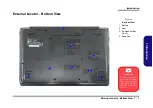
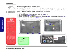
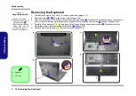
Figure 2
HDD Assembly
Removal
a. Remove the screws.
b. Remove the bay cover.
c. Locate the HDD assem-
bly.
HDD System Warning
New HDD’s are blank.
Before you begin make
sure:
You have backed up
any data you want to
keep from your old
HDD.
You have all the CD-
ROMs and FDDs re-
quired to install your op-
erating system and
programs.
If you have access to
the internet, download
the latest application
and hardware driver up-
dates for the operating
system you plan to in-
stall. Copy these to a re-
movable medium.
1.
Turn
off
the computer, turn it over to remove the battery (
2.
Remove the screws
-
).
3.
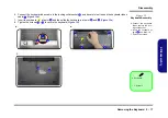
Slide the component bay cover
until the cover and case indicator
are aligned and remove it (
).
4.
The hard disk drive will be visible at point
(
)
.
1
4
5
6
7
a.
b.
5. HDD Bay Cover
•
4 Screws
2
3
4
1
6
7
c.
5
Summary of Contents for N650DU Series
Page 1: ...N650DU ...
Page 2: ......
Page 3: ...Preface I Preface Notebook Computer N650DU Service Manual ...
Page 24: ...Introduction 1 12 1 Introduction ...
Page 48: ...Disassembly 2 24 Removing the CCD 2 Disassembly ...
Page 51: ...Top A 3 A Part Lists Top Figure A 1 Top ...
Page 52: ...A 4 Bottom A Part Lists Bottom Figure A 2 Bottom ...
Page 53: ...LCD A 5 A Part Lists LCD Figure A 3 LCD ...
Page 54: ...A 6 DVD A Part Lists DVD Figure A 4 DVD ...
Page 55: ...HDD A 7 A Part Lists HDD Figure A 5 HDD ...
Page 56: ...A 8 2nd HDD A Part Lists 2nd HDD Figure A 6 2nd HDD ...
Page 57: ...MB A 9 A Part Lists MB Figure A 7 HDD ...
Page 58: ...A 10 A Part Lists ...
Page 104: ...Schematic Diagrams B 46 B Schematic Diagrams ...

