Disassembly
2 - 10 Removing the Optical Device
2.Disassembly
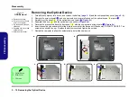
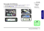
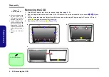
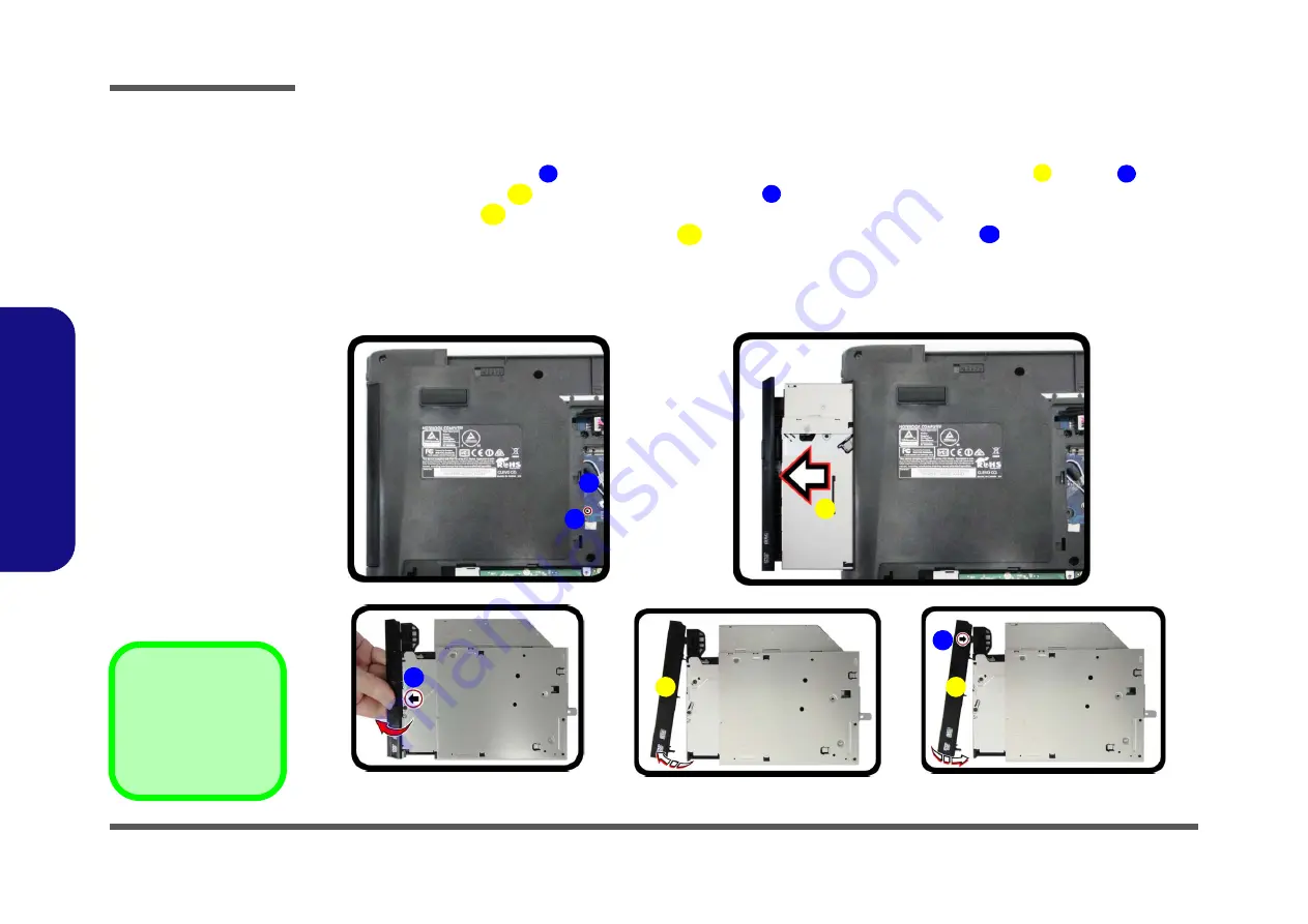
Removing the Optical Device
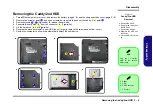
Figure 6
ODD Removal
a. Remove the screw.
b. Push the optical device
out of the computer.
c. Pry the bezel off the opti-
cal device.
d. Separate the bezel and
optical device
e. Install the front bezel.
1.
Turn
off
the computer, turn it over, and remove the battery (
) and the component bay cover (
).
2.
Remove the screw at point
, and use a screwdriver to carefully push out the optical device
at point
.
3.
Carefully pry the bezel
off the optical device at point
(
)
.
4.
Separate the bezel
and the optical device as shown (
).
5.
Reverse the process to attach the front bezel
with the new optical device at point
).
6.
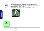
Insert the new device and carefully slide it into the computer (the device only fits one way. DO NOT FORCE IT; The
screw holes should line up). Replace the bottom cover and tighten the screws.
7.
Restart the computer to allow it to automatically detect the new device.
1
3
2
5
4
5
5
6
b.
a.
2
3
1
e.
c.
d.
4
6
5
5
3. Optical Device
5. Bezel Cover
•
1 Screws
Summary of Contents for N650DU Series
Page 1: ...N650DU ...
Page 2: ......
Page 3: ...Preface I Preface Notebook Computer N650DU Service Manual ...
Page 24: ...Introduction 1 12 1 Introduction ...
Page 48: ...Disassembly 2 24 Removing the CCD 2 Disassembly ...
Page 51: ...Top A 3 A Part Lists Top Figure A 1 Top ...
Page 52: ...A 4 Bottom A Part Lists Bottom Figure A 2 Bottom ...
Page 53: ...LCD A 5 A Part Lists LCD Figure A 3 LCD ...
Page 54: ...A 6 DVD A Part Lists DVD Figure A 4 DVD ...
Page 55: ...HDD A 7 A Part Lists HDD Figure A 5 HDD ...
Page 56: ...A 8 2nd HDD A Part Lists 2nd HDD Figure A 6 2nd HDD ...
Page 57: ...MB A 9 A Part Lists MB Figure A 7 HDD ...
Page 58: ...A 10 A Part Lists ...
Page 104: ...Schematic Diagrams B 46 B Schematic Diagrams ...

